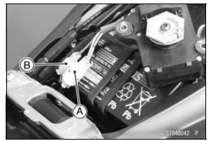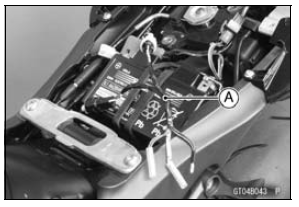

NOTE
Before this inspection, confirm the pulley is original position (see Exhaust Butterfly Valve Actuator Installation).

Special Tool - Throttle Sensor Setting Adapter #1: 57001 -1400
Exhaust Butterfly Valve Actuator Sensor Output Voltage Connections to Adapter: Digital Meter (+) → BL (actuator Y) lead Digital Meter (−) → BK/BL (actuator BK) lead

Output Voltage
Standard: DC 3.46  3.76 V at pulley
original position
If the reading is out of the standard, check the exhaust butterfly valve actuator sensor resistance (see Exhaust Butterfly Valve Actuator Sensor Resistance Inspection).
If the reading is within the standard, remove the ECU and check the wiring for continuity between main harness connectors.
Disconnect the ECU and sensor connectors
Wiring Inspection ECU Connector [A] ←→ Exhaust Butterfly Valve Actuator Sensor Connector [B] GY lead (ECU terminal 24) [C] BR/BK lead (ECU terminal 13) [D]

If the wiring is good, check the ECU for its ground and power supply (see ECU Power Supply Inspection in the Fuel System (DFI) chapter).
If the ground and power supply are good, replace the ECU (see ECU Removal/Installation in the Fuel System (DFI) chapter).
 Exhaust Butterfly Valve Actuator Sensor Input Voltage Inspection
 Exhaust Butterfly Valve Actuator Sensor Resistance Inspection
Cam Wear Inspection
Remove the camshafts (see Camshaft Removal).
Measure the height [A] of each cam with a micrometer.
If the cams are worn down past the service limit, replace
the camshaft.
Cam Height
Standard:
Exhaust 35.043 35.157 mm
(1.3796 1.3841 in.)
Intake 38.243 38.357 mm
(1.5056 1.5101 in. ...
Related Parts Locations
KIBS Control
1. ABS performance equivalent to the current model (enhanced braking
stability)
By monitoring front caliper hydraulic pressure, KIBS regulates pressure
increases reducing the tendency
of the rear to lift. Before the ABS system fully reacts, KIBS system prevents
the pressure ...
Headlight Aiming Adjustment
NOTE
Do not turn the bolts [A] because the reflector in the
headlight comes off.
(In the photo, the headlight unit has been removed for
clarity.)
NOTE
The left adjuster [A] and right adjuster [B] can move the
direction of the headlight beam to up, down, left and
right by turning each a ...