
7. US, CA and CAL Models
8. Immobilizer System Equipped Models
9. ZX1000JD/KD
AD: Apply adhesive.
L: Apply a non-permanent locking agent.
R: Replacement Parts
13. Other than US, CA and CAL Models
CL: Apply cable lubricant.
EO: Apply engine oil.
G: Apply grease.
L: Apply a non-permanent locking agent.
R: Replacement Parts
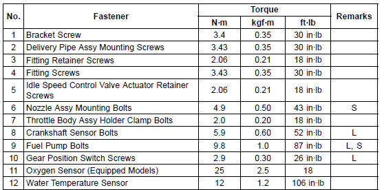
S: Follow the specified tightening sequence.
3. Other than CAL and SEA-B1 Models
4. CAL and SEA-B1 Models
 DFI System
KIBS Motor Relay Inspection (Service Code b 35)
Check the KIBS motor relay fuse (25 A) [A] (see Fuse
Inspection in the Electrical System chapter)
If the fuse is good, check the wiring continuity as follows.
Disconnect:
Battery Positive Cable (see Battery Removal in the Electrical
System chapter)
KIBS Hydraulic Unit Lead Connector (see ...
Water Pump Housing Disassembly
NOTICE
Do not damage the hole wall of the water pump
housing.
Insert a bar [A] into the pump housing [B], and hammer
evenly around the circumference of the mechanical seal
bottom [C].
Take the oil seal [A] out of the housing [B] with a hook [C].
...
Alternator Rotor Removal
Remove the alternator cover (see Alternator Cover Removal).
Clean off the oil from the outer circumference of the rotor.
Hold the alternator rotor steady with the rotor holder [A]
and suitable washer or plate [B].
Special Tools - Grip [C]: 57001-1591
Rotor Holder: 57001-1666
Flywheel P ...
