
14. Thermostat
15. Frame No.  JKAZXT00JJA003074
or  JKAZXCJ1
BA003074
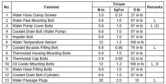
G: Apply grease.
HG: Apply high-temperature grease.
L: Apply a non-permanent locking agent.
R: Replacement Parts
S: Follow the specified tightening sequence.
W: Apply water.
1. US, CA and CAL Models
2. Frame No.  JKAZXT00JJA003074
or  JKAZXCJ1
BA003074
3. Engine No.  ZXT00JE003022
L: Apply a non-permanent locking agent.
 Cooling System
 Coolant Flow Chart
Engine Removal
Support the rear part of the swingarm with a stand.
Squeeze the brake lever slowly and hold it with a band
[A].
WARNINGMotorcycle may fall over unexpectedly
resulting in
an accident or injury. Be sure to hold the front brake
when removing the engine.
NOTICE
Be sure ...
Storage of Removed Parts
After all the parts including subassembly parts have been
cleaned, store the parts in a clean area. Put a clean cloth
or plastic sheet over the parts to protect from any foreign
materials that may collect before re-assembly.
Inspection
Reuse of worn or damaged parts may lead to serious acci ...
Fuel Tank Cleaning
WARNINGGasoline and low flash-point solvents can
be
flammable and/or explosive and cause severe
burns. Clean the tank in a well-ventilated area, and
take care that there are no sparks or flame anywhere
near the working area. Do not use gasoline
or low flash-point solvents t ...