
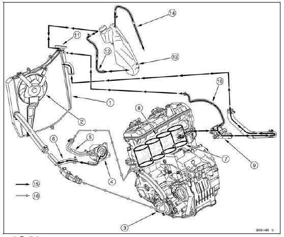
1. Radiator
2. Radiator Fan
3. Water Pump
4. Oil Cooler
5. Oil Cooler Intake Hose
6. Oil Cooler Outlet Hose
7. Cylinder Jacket
8. Cylinder Head Jacket
9. Thermostat Housing
10. Air Bleeder Hose
11. Radiator Cap
12. Radiator Overflow Hose
13. Reserve Tank
14. Reserve Tank Overflow Hose
15. Hot Coolant
16. Cold Coolant
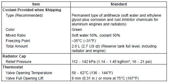
Permanent type antifreeze is used as a coolant to protect the cooling system from rust and corrosion.
When the engine starts, the water pump turns and the coolant circulates.
The thermostat is a wax pellet type which opens or closes with coolant temperature changes. The thermostat continuously changes its valve opening to keep the coolant temperature at the proper level.
When coolant temperature is less than 55°C (131°F), the thermostat closes so that the coolant flow is restricted through the air bleeder hole, causing the engine to warm up more quickly. When coolant temperature is more than 58 ∼ 62°C (136 ∼ 144°F), the thermostat opens and the coolant flows.
When the coolant temperature goes up beyond 95°C (203°F), the radiator fan relay conducts to operate the radiator fan. The radiator fan draws air through the radiator core when there is not sufficient air flow such as at low speeds. This increases up the cooling action of the radiator. When the coolant temperature is below 90°C (194°F), the fan relay opens and the radiator fan stops.
In this way, this system controls the engine temperature within narrow limits where the engine operates most efficiently even if the engine load varies.
The system is pressurized by the radiator cap to suppress boiling and the resultant air bubbles which can cause engine overheating. As the engine warms up, the coolant in the radiator and the water jacket expands. The excess coolant flows through the radiator cap and hose to the reserve tank to be stored there temporarily. Conversely, as the engine cools down, the coolant in the radiator and the water jacket contracts, and the stored coolant flows back to the radiator from the reserve tank.
The radiator cap has two valves. One is a pressure valve which holds the
pressure in the system
when the engine is running. When the pressure exceeds 112
 142 kPa (1.14
 1.45 kgf/cm², 16
 21
21
psi), the pressure valve opens and releases the pressure to the reserve tank. As
soon as pressure
escapes, the valve closes, and keeps the pressure at 112
 142 kPa (1.14
 1.45 kgf/cm², 16
 21 psi).
When the engine cools down, another small valve (vacuum valve) in the cap opens. As the coolant cools, the coolant contracts to form a vacuum in the system. The vacuum valve opens and allows the coolant from the reserve tank to enter the radiator.
Specifications
Special Tools
Bearing Driver Set:
57001-1129 
Oil Seal Driver 37.5:
57001-1660 
 Exploded View
 Coolant
Thermostat Installation
Replace the O-rings [A] with new ones, and apply grease
to them.
Assemble:
O-rings
Thermostat Housing [B]
Thermostat [C]
Thermostat Cap [D]
Install the thermostat [A] in the housing so that the air
bleeder hole [B] is on top.
Tighten:
Torque - Thermostat Cap Bolts: 5.9 N ...
Throttle Body Assy Disassembly
1. Throttle Body Assy
2. Subthrottle Valve Actuator
3. Idle Speed Control Valve Actuator
4. Main Throttle Sensor
5. Subthrottle Sensor
6. Primary Fuel Injectors
7. Delivery Pipe Assy
NOTICE
Do not remove, disassemble or adjust the main
throttle sensor, subthrottle sensor, subthrottle
v ...
Multifunction Meter
A. Multifunction Display
Odometer
Trip Meters
Current Mileage
Average Mileage
Fuel consumption
Stop Watch
B. Speedometer
C. Gear Position Indicator
D. Power Mode Indicator
E. S-KTRC Mode Indicator
F. Warning Symbols
G. Lap Counter/Coolant /
Intake Air Temperature
Meter
...