
25. “1T” marked side faces up.
26. “T2” marked side faces up.
27. Hollow mark faces exhaust side.
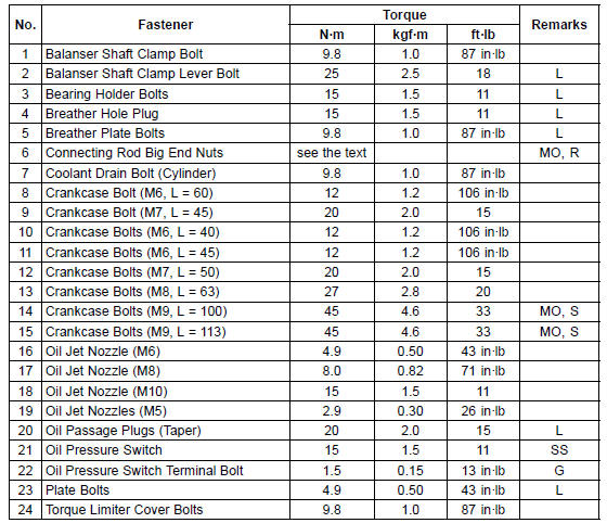
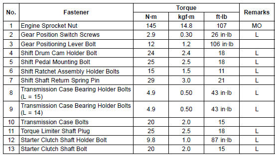
G: Apply grease.
L: Apply a non-permanent locking agent.
LG: Apply liquid gasket.
M: Apply molybdenum disulfide grease.
MO: Apply molybdenum disulfide oil solution.
(mixture of the engine oil and molybdenum disulfide grease in a weight ratio 10:1) R: Replacement Parts
S: Follow the specified tightening sequence.
SS: Apply silicone sealant.
WL: Apply soap and water solution or rubber lubricant.
14. Frame No. JKAZXCJ1CA011772 ∼ G: Apply grease.
L: Apply a non-permanent locking agent.
MO: Apply molybdenum disulfide oil solution.
(mixture of the engine oil and molybdenum disulfide grease in a weight ratio 10:1) R: Replacement Parts
 Specifications
Lower Fairing Removal
Remove the quick rivets [A].
Remove:
Quick Rivets [A]
Bolts [B]
Pull up the core by the flat-head screwdriver (–), and then
remove the quick rivet.
Clear the hook portions on the upper edges [C] from the
slots, and remove the left lower fairing [D].
While pulling down ...
For Primary Fuel Injectors
Remove the air cleaner housing (see Air Cleaner Housing
Removal).
Disconnect the injector connector and connect the harness
adapter [A] between these connectors as shown in
the figure.
Main Harness [B]
Primary Fuel Injector #1 [C]
Special Tool - Measuring Adapter: 57001-1700
...
Switch Inspection
Using a hand tester, check to see that only the connections
shown in the table have continuity.
Special Tool - Hand Tester: 57001-1394
For the switch housings and the ignition switch, refer to
the tables in the Wiring Diagram.
If the switch has an open or short, repair it or replace it
w ...
