
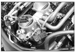
Disconnect the main throttle sensor connector and connect the setting adapter [A] between these connectors.
Special Tool - Throttle Sensor Setting Adapter: 57001 -1538
Main Throttle Sensor Output Voltage Connections to Adapter: Digital Meter (+) → R (sensor V/W) lead
Digital Meter (–) → BK (sensor BR/BK) lead
Install the following parts temporarily.
Throttle Body Assy (see Throttle Body Assy Installation in the Fuel System (DFI) chapter) Air Cleaner Housing (see Air Cleaner Housing Installation in the Fuel System (DFI) chapter) Fuel Tank (see Fuel Tank Installation in the Fuel System (DFI) chapter)
Throttle Sensor Setting Adapter [A]
Idle Speed Standard: 1 100 ±50 r/min (rpm)
Output Voltage
Standard: DC 0.64 0.68 V at idle
throttle opening
DC 3.89  4.09 V at full throttle
opening (for
reference)
NOTE
Example: In the case of a input voltage of 4.75 V.
0.64 × 4.75 ÷ 5.00 = 0.61 V
0.68 × 4.75 ÷ 5.00 = 0.65 V
Thus, the valid range is 0.61
0.65 V
If the reading is out of the standard, replace the throttle body assy.
If the reading is within the standard, remove the ECU and check the wiring for continuity between harness connectors.
Special Tool - Hand Tester: 57001-1394
Disconnect the ECU and sensor connectors.
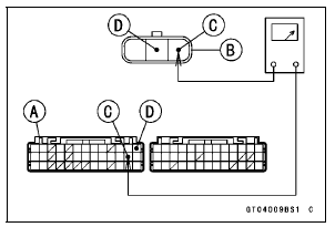
Wiring Continuity Inspection ECU Connector [A] ←→ Main Throttle Sensor Connector [B] V/W lead (ECU terminal 25) [C] BR/BK lead (ECU terminal 13) [D]
If the wiring is good, check the ECU for its ground and power supply (see ECU Power Supply Inspection in the Fuel System (DFI) chapter).
If the ground and power supply are good, replace the ECU (see ECU Removal/Installation in the Fuel System (DFI) chapter).
Main Throttle Sensor Circuit
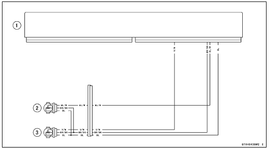
1. ECU
2. Subthrottle Sensor
3. Main Throttle Sensor
 Main Throttle Sensor Resistance Inspection
Stick Coil Inspection
Remove the stick coils (see Stick Coil Removal).
Measure the primary winding resistance [A] as follows.
Connect the hand tester between the coil terminals.
Set the tester to the × 1 Ω range, and read the tester.
Measure the secondary winding resistance [B] as follows.
Conn ...
Rear Turn Signal Light Bulb Replacement
Remove the upper seat cover (see Seat Cover Removal
in the Frame chapter).
Disconnect the tail/brake light connector [A].
Turn the socket [A] counterclockwise and remove the
socket together with the bulb.
Push and turn the turn signal light bulb [A] counterclockwise
an ...
Vehicle-down Sensor Installation
Be sure to install the rubber dampers [A] and collars [B]
on the bracket.
The UP mark [A] of the sensor should face upward.
WARNINGIncorrect installation of the vehicle-down
sensor
could cause sudden loss of engine power. The
rider could lose balance during certain ...
