
NOTE
Be sure the battery is fully charged.
Main Harness [B] Fuel Pump [C]
Special Tool - Measuring Adapter: 57001-1700
Fuel Pump Operating Voltage Connections to Adapter:
Digital Meter (+) → R (pump Y/R) lead
Digital Meter (–) → BK (pump BK/W) lead
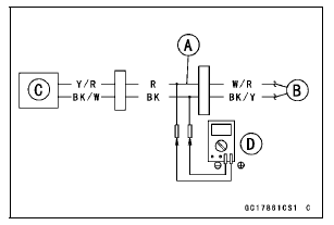
Operating Voltage Standard: Battery Voltage for 3 seconds, and then 0 V
If the reading stays on battery voltage and never shows 0 V, check the fuel pump relay (see Relay Circuit Inspection in the Electrical System chapter).
If the fuel pump relay is normal, check the ECU for its ground and power supply (see ECU Power Supply Inspection).
If the ground and power supply are good, replace the ECU (see ECU Removal/Installation).
If there is still no battery voltage, check the fuel pump relay (see Relay Circuit Inspection in the Electrical System chapter).
If the fuel pump relay is normal, check the wiring for continuity (see wiring diagram in this section).
Special Tool - Hand Tester: 57001-1394
If the wiring is good, check the ECU for its ground and power supply (see ECU Power Supply Inspection).
If the ground and power supply are good, replace the ECU (see ECU Removal/Installation).
If the reading is in specification, but the pump does not operate, replace the fuel pump (see Fuel Pump Removal/Installation).
 Fuel Pump Operation Inspection
 Pressure Regulator Removal
Engine Oil Change
Situate the motorcycle so that it is vertical after warming
up the engine.
Remove the engine oil drain bolt [A] to drain the oil.
The oil in the oil filter can be drained by removing the filter
(see Oil Filter Replacement).
Replace the drain bolt gasket [B] with a new one.
Tighten t ...
Spark Plug Condition Inspection
Remove the spark plugs (see Spark Plug Replacement in
the Periodic Maintenance chapter).
Visually inspect the spark plugs.
If the spark plug center electrode [A] and/or side electrode
[B] are corroded or damaged, or if the insulator [C]
is cracked, replace the plug.
If the spark plug is ...
Tire Installation
WARNINGSome replacement tires may adversely
affect handling
and cause an accident resulting in serious injury
or death. To ensure proper handling and stability,
use only the recommended standard tires for
replacement, inflated to the standard pressure.
Inspect the rim ...