
NOTICE
Do not turn the compression damping force adjuster beyond the fully seated position or the adjusting mechanism may be damaged.
A. Compression Damping Force Adjuster for High Speed
B. To increase damping force
C. To decrease damping force
Compression Damping Force Setting for High and Low Speeds
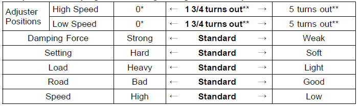
*: This position is the fully seated position (turned fully clockwise).
**: Out from the fully seated position (turned fully clockwise). This adjustment range may not exactly match the number shown in the table due to small tolerance of production.
The standard suspension setting positions are as follows:
Standard Setting Position (Rear Shock Absorber)
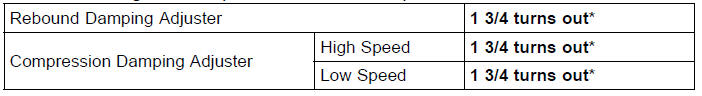
*: Out from the fully seated position (turned fully clockwise)
 Compression Damping Force Adjustment
 Wheels
Engine Installation
Apply molybdenum disulfide grease to the threads of the
adjusting collars [A].
Install the adjusting collars to crankcase backside until
end of the threads.
Install the adjusting collar [A] to the frame until end of the
threads.
Replace the engine mounting nuts with ne ...
Fuel Injector Output Voltage Inspection
NOTE
Be sure the battery is fully charged.
Turn the ignition switch to OFF.
Remove the ECU (see ECU Removal).
Do not disconnect the ECU connector
Connect a digital meter [A] to the connector (gray) [B] with
the needle adapter set.
Special Tool - Needle Adapter Set: 57001-1457
...
External Shift Mechanism Inspection
Examine the shift shaft [A] for any damage.
If the shaft is bent, straighten or replace it.
If the serration [B] are damaged, replace the shaft.
If the spring [C] is damaged in any way, replace it.
If the shift mechanism arm [D] is damaged in any way,
replace the shaft.
Check the s ...