
DFI Diagnosis Flow Chart
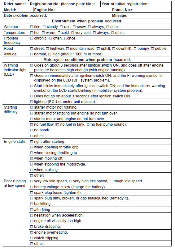
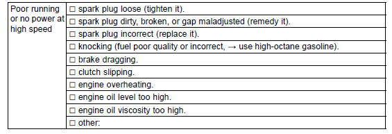
Sample Diagnosis Sheet
 Outline
 DFI System Troubleshooting Guide
KIBS Hydraulic Unit Installation
NOTICE
Brake fluid quickly ruins painted plastic surfaces;
any spilled fluid should be completely washed away
immediately.
Install the KIBS hydraulic unit together with the bracket.
Before installing the brake pipe, check to see that there is
no damage on the threads of the brake pipe joi ...
Exploded View
10. US, CA, CAL and AU Models
11. ZX1000JD/KD
G: Apply grease.
L: Apply a non-permanent locking agent.
R: Replacement Parts
S: Follow the specified tightening sequence.
1. US, CA and CAL Models
2. ZX1000J Model
3. ZX1000K Model
4. AU Model
5. Face the large diameter side re ...
Location of labels
All warning labels which are on your
vehicle are repeated here. Read labels
on your vehicle and understand them
thoroughly. They contain information
which is important for your safety and
the safety of anyone else who may operate
your vehicle. Therefore, it is very
important that all warning ...