
Insert the needle bearing driver [A] into the needle bearing [B] and press the needle bearing into the housing until the driver contacts the end surface of the housing.
NOTE
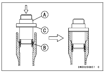
Special Tools - Bearing Driver Set: 57001-1129
Needle Bearing Driver,  28:
28:
57001-1610
Spacer 28: 57001-1663
Needle Bearing Driver,  20 &
20 &
Spacer,  28
28
(Spacer): 57001-1678
Press in the ball bearing until it bottomed.
Special Tool - Bearing Driver Set: 57001-1129
Special Tool - Inside Circlip Pliers: 57001-143
Special Tool - Bearing Driver Set: 57001-1129
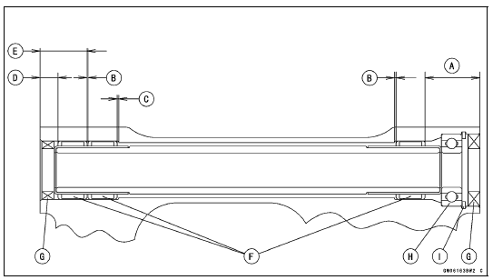
32 mm (1.26 in.) [A] 1 mm (0.04 in.) [B] 1.5 mm (0.06 in.) [C] 9.5 mm (0.37 in.) [D] 27.5 mm (1.08 in.) [E] Needle Bearings [F] Grease Seals [G] Ball Bearing [H] Circlip [I]
 Swingarm Bearing Removal
 Swingarm Bearing, Sleeve Inspection
Steering Stem Bearing Lubrication
Remove the steering stem (see Stem, Stem Bearing Removal
in the Steering chapter).
Using a high flash-point solvent, wash the upper and
lower ball bearings [A] in the cages.
Wipe the upper and lower outer races which are press
-fitted into the head pipe to clean off grease and dirt.
V ...
Battery
The battery installed in this motorcycle
is a sealed type, so it is not necessary
to check the battery electrolyte
level or add distilled water.
The sealing strip should not be pulled
off once the specified electrolyte has
been installed in the battery for initial
service.
However, in or ...
Gear Position Switch Inspection
NOTE
Be sure the transmission and external shift mechanism
are good condition.
Remove the fuel tank (see Fuel Tank Removal in the Fuel
System (DFI) chapter).
Disconnect the connector [A].
Set the hand tester [A] to the × 1 kΩ or × 100 Ω range
and connect i ...