
NOTE
Be sure the battery is fully charged.
[B] Main Harness
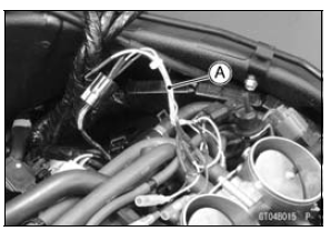
[C] Intake Air Pressure Sensor #1
Special Tool - Measuring Adapter: 57001-1700
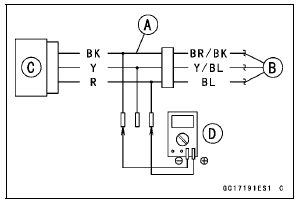
Intake Air Pressure Sensor #1 Input Voltage Connections to Adapter: Digital Meter (+) → R (sensor BL) lead Digital Meter (‚Äì) → BK (sensor BR/BK) lead
Input Voltage Standard: DC 4.75 ∼ 5.25 V
If the reading is within the standard, check the output voltage (see Intake Air Pressure Sensor #1 Output Voltage Inspection).
If the reading is out of the standard, remove the ECU and check the wiring for continuity between main harness connectors.
Special Tool - Hand Tester: 57001-1394
Disconnect the ECU and sensor connectors.
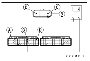
Wiring Continuity Inspection ECU Connector [A] ←→ Intake Air Pressure Sensor #1 Connector [B] BL lead (ECU terminal 9) [C] BR/BK lead (ECU terminal 13) [D]
If the wiring is good, check the ECU for its ground and power supply (see ECU Power Supply Inspection in the Fuel System (DFI) chapter).
If the ground and power supply are good, replace the ECU (see ECU Removal/Installation in the Fuel System (DFI) chapter).
 Intake Air Pressure Sensor #1 Installation
 Intake Air Pressure Sensor #1 Output Voltage Inspection
Meter Operation Inspection
Check 1-1: Switching Inspection
Turn the ignition switch to ON and check the following.
The all LCD segments [A] appear for 3 seconds.
The warning indicator light (Red LED) [B] goes on for 3
seconds and then goes off in a moment after that goes
off.
The warning indicator light (Yellow LED ...
ESD (Electronic Steering Damper) ECU Communication Error (Service Code 3C,
ZX1000JD/KD)
ESD ECU Communication Line Inspection
When the data (for status of ESD system) is not sent from
the ESD ECU to the meter unit and ECU, the service code
3C is displayed.
The data is sent through the CAN communication line.
The service code 3C is detected with the meter unit.
The FI symbol does ...
Odometer
The odometer shows the total distance
in kilometers or miles that the vehicle
has run. If the odometer is displayed,
the “ODO” is displayed on the
multifunction display. This meter cannot
be reset.
A. Odometer
B. “ODO”
NOTE
The data are maintained even if the
battery is disco ...