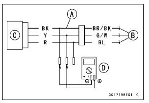

Disconnect the intake air pressure sensor #2 connector and connect the measuring adapter [A] between these connectors.
[B] Main Harness [C] Intake Air Pressure Sensor #2 [D] Digital Meter

Special Tool - Measuring Adapter: 57001-1700
Intake Air Pressure Sensor #2 Output Voltage Connections to Adapter: Digital Meter (+) → Y (sensor G/W) lead Digital Meter (–) → BK (sensor BR/BK) lead

Output Voltage
Usable Range: DC 3.80  4.20 V at
standard
atmospheric pressure (101.32 kPa, 76
cmHg absolute)
NOTE
The output voltage changes according to the local atmospheric pressure.
If the reading is out of the usable range, replace the sensor.
If the reading is within the usable range, remove the ECU and check the wiring for continuity between main harness connector.
Special Tool - Hand Tester: 57001-1394
Disconnect the ECU and sensor connectors.

Wiring Continuity Inspection ECU Connector [A] ←→ Intake Air Pressure Sensor #2 Connector [B] G/W lead (ECU terminal 11) [C] BR/BK lead (ECU terminal 13) [D]
If the wiring is good, check the sensor for various vacuum (see Intake Air Pressure Sensor #1 Output Voltage Inspection).
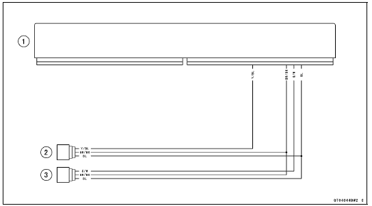
Intake Air Pressure Sensor #2 Circuit

1. ECU
2. Intake Air Pressure Sensor #1
3. Intake Air Pressure Sensor #2
The crankshaft sensor has no power source, and when the engine stops, the crankshaft sensor generates no signals.
 Intake Air Pressure Sensor #2 Input Voltage Inspection
 Crankshaft Sensor (Service Code 21)
Clutch Installation
Apply engine oil to the needle bearing [A] and the sleeve
[B].
Install:
Needle Bearing
Sleeve
Install the clutch housing [A].
Fit the holes [B] and projections [C].
Engage the clutch housing gear and the crankshaft primary
gear.
Install the spacer [A] and the clutch ...
Swingarm Bearing, Sleeve Inspection
NOTICE
Do not remove the bearings for inspection. Removal
may damage them.
Inspect the needle bearings [A] and ball bearing installed
in the swingarm.
The rollers and ball in a bearing normally wear very little,
and wear is difficult to measure. Instead of measuring,
visually inspec ...
Seat Cover Removal
Remove:
Rear Seat (see Rear Seat Removal)
Remove the bolts [A].
Remove the upper seat cover backward [B] to clear the
hook portions.
Remove:
Front Seat (see Front Seat Removal)
Quick Rivets [A]
Bolts [B]
Seat Covers [C]
...