

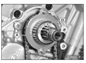
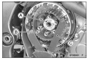
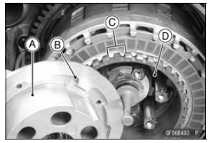
Fit the holes [B] and projections [C].
Engage the clutch housing gear and the crankshaft primary gear.
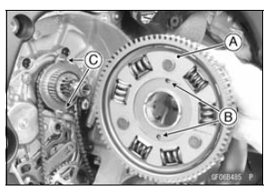
Turn the stepped side [C] of the spacer to outside.
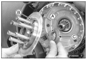
If the sub clutch hub bolts were removed, install them as follows.
Apply a non-permanent locking agent to the threads of the sub clutch hub bolts, and tighten them.
Torque - Sub Clutch Hub Bolts: 25 N·m (2.5 kgf·m, 18 ft·lb)
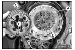
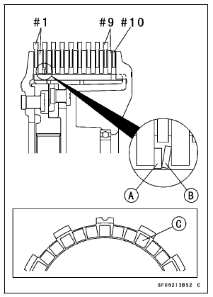
First Torque Limiter Spring [A] Tang [B]
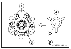
Second Torque Limiter Spring [A] Tang [B]
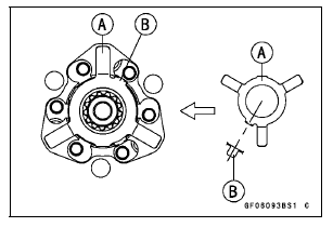
Third Torque Limiter Spring [A] Tang [B]
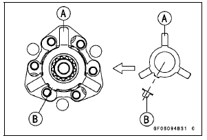
Fourth Torque Limiter Spring [A] Tang [B]
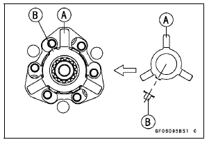
Special Tool - Clutch Holder: 57001-1243
Torque - Clutch Hub Nut: 130 N·m (13.3 kgf·m, 96 ft·lb)
Friction Plates (48 Lining Blocks) [#1, #10]
Friction Plates (36 Lining Blocks) [#2
 #9]
#9]
Steel Plates (T = 2.9) [#1  #7]
#7]
Steel Plates (T = 2.6) [#8, #9]
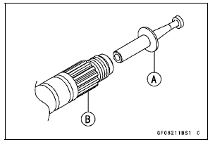
Spring Seat [A]
Spring [B]
NOTE
 #9].
#9].
NOTICE
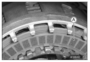
If new dry friction plates and steel plates are installed, apply engine oil to the surfaces of each plate to avoid clutch plate seizure.
Torque - Clutch Spring Bolts: 11 N·m (1.1 kgf·m, 97 in·lb)
 Clutch Removal
 Spring Plate Free Play Measurement
Alternator Rotor Installation
Using a cleaning fluid, clean off any oil or dirt on the following
portions and dry them with a clean cloth.
Crankshaft Tapered Portion [A]
Alternator Rotor Tapered Portion [B]
Install the alternator rotor.
Using a cleaning fluid, clean off any oil or dirt on the
washer [A] ...
Odometer
The odometer shows the total distance
in kilometers or miles that the vehicle
has run. If the odometer is displayed,
the “ODO” is displayed on the
multifunction display. This meter cannot
be reset.
A. Odometer
B. “ODO”
NOTE
The data are maintained even if the
battery is disco ...
Seat Cutter Operation Care
1. This valve seat cutter is developed to grind the valve for
repair. Therefore the cutter must not be used for other
purposes than seat repair.
2. Do not drop or shock the valve seat cutter, or the diamond
particles may fall off.
3. Do not fail to apply engine oil to the valve seat cutter
...