
If your motorcycle battery is ŌĆ£run downŌĆØ, it should be removed and charged. If this is not practical, a 12 volt booster battery and jumper cables may be used to start the engine.
DANGER
Battery acid generates hydrogen gas which is flammable and explosive under certain conditions.
It is present within a battery at all times, even in a discharged condition. Keep all flames and sparks (cigarettes) away from the battery. Wear eye protection when working with a battery. In the event of battery acid contact with skin, eyes, or clothing, wash the affected areas immediately with water for at least 5 minutes. Seek medical attention.
Connecting Jumper Cables
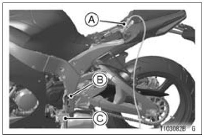
A. From Booster Battery Positive (+) Terminal
B. Swingarm Pivot
C. From Booster Battery Negative (ŌĆō) Terminal
DANGER
Batteries contain sulfuric acid that can cause burns and produce hydrogen gas which is highly explosive. Do not make this last connection at the fuel system or battery. Take care not to touch the positive and negative cables together, and do not lean over the battery when making this last connection. Do not connect to a frozen battery. It could explode. Do not reverse polarity by connecting positive (+) to negative (ŌĆō), or a battery explosion and serious damage to the electrical system may occur.
NOTICE
Do not operate the starter continuously for more than 5 seconds or the starter will overheat and the battery power will drop temporarily. Wait 15 seconds between each operation of the starter to let it cool and the battery power recover.
 Starting the Engine
 Moving Off
Operating Procedures
Clean the seat area carefully.
Coat the seat with machinistŌĆÖs dye.
Fit a 45┬░ cutter into the holder and slide it into the valve
guide.
Press down lightly on the handle and turn it right or left.
Grind the seating surface only until it is smooth.
NOTICE
Do not grind the seat too ...
Rear Frame Front Removal
Remove:
Rear Frame Rear (see Rear Frame Rear Removal)
Rear Fender Front (see Rear Fender Front Removal)
Rear Footpeg Bracket Bolts [A]
Rear Footpeg Bracket [B]
Rear Frame Front Bolts [C]
Left Rear Frame Front [D]
Remove:
Rear Footpeg Bracket Bolts [A]
Rear Footpeg Bracke ...
Stick Coil Inspection
Remove the stick coils (see Stick Coil Removal).
Measure the primary winding resistance [A] as follows.
Connect the hand tester between the coil terminals.
Set the tester to the × 1 Ω range, and read the tester.
Measure the secondary winding resistance [B] as follows.
Conn ...