
If the connector is clogged with mud or dust, blow it off with compressed air.
If the terminals of the main harness connectors are damaged, replace the main harness.
If the terminals of the ECU connectors are damaged, replace the ECU.
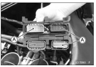
Gray Connector [A]
Special Tool - Hand Tester: 57001-1394
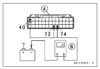
ECU Grounding Inspection
Connections:
(I) BK/Y leads (ECU terminal 40, 73 or 74) ←→ Battery (–) Terminal
(II) Engine Ground ←→ Battery (–) Terminal
Criteria: Both: 0 Ω
If no continuity, check the connectors, the engine ground lead, or main harness, and repair or replace them if necessary.
If the wiring is good, check the power source voltage of the ECU.
NOTE
Be sure the battery is fully charged.
Special Tool - Needle Adapter Set: 57001-1457
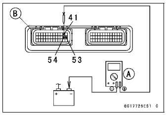
ECU Power Supply Inspection Connections:
(I) Digital Meter (+) → Terminal 41 (W/BK)
Digital Meter (–) → Battery (–) terminal
(II) Digital Meter (+) → Terminal 53 (BR/W)
Digital Meter (–) → Battery (–) terminal
(III) Digital Meter (+) → Terminal 54 (W/BK)
Digital Meter (–) → Battery (–) terminal
Ignition Switch OFF:
Terminal 41 (W/BK): Battery Voltage
Terminal 53 (BR/W): 0 V
Terminal 54 (W/BK): Battery Voltage
Ignition Switch ON:
All: Battery Voltage
If the reading is out of the specification, check the following.
Main Fuse 30 A (see Fuse Inspection in the Electrical System chapter)
ECU Fuse 15 A (see Fuse Inspection in the Electrical System chapter)
ECU Main Relay (see Relay Circuit Inspection in the Electrical System chapter)
Power Source Wiring (see wiring diagram in this section)
If the fuse, wiring and relay are good, replace the ECU (see ECU Removal/Installation).
 ECU Removal
 ECU Power Source Circuit
Exhaust Butterfly Valve Cable Installation
Confirm whether pulley [A] is an angle shown in the figure.
41.7° ±7° [B]
This position is original position of the pulley.
NOTE
Correct the position electrically after confirming the use
is discontinued and there is no damage when differing
from the angle of shown in the figure.
...
Oil Seal, Grease Seal
Do not remove pressed oil or grease seals unless removal
is necessary. Replace with new ones whenever removed.
Press new oil seals with manufacture and size marks facing
out. Make sure the seal is aligned properly when installing.
Apply specified grease to the lip of seal before installing ...
Fuel Hose Inspection (fuel leak, damage, installation condition)
If the motorcycle is not properly handled, the high pressure
inside the fuel line can cause fuel to leak [A] or the
hose to burst. Remove the fuel tank (see Fuel Tank Removal
in the Fuel System (DFI) chapter) and check the
fuel hoses.
Replace the fuel hose if any fraying, cracks [B] or ...