
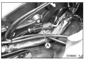
Rear Wheel Rotation Sensor Lead Connector [A] KIBS Hydraulic Unit Lead Connector [B] G Lead Terminals [C] R Lead terminals [D]
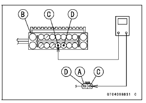
If the wiring is open, replace or repair the harness (see KIBS System Circuit in the Brakes chapter).
If the wiring is good, go to next step.
If this service code appears even if all checks are ended, replace the rear wheel rotation sensor (see Rear Wheel Rotation Sensor Removal in the Brakes chapter).
If the service code does not appear, the KIBS system normal (temporary failure).
 Rear Wheel Rotation Sensor Signal Abnormal (Service Code b 44)
 Power Supply Voltage Inspection (Low-Voltage) (Service Code b 52)
Transmission Assy Installation
Assemble the transmission assy (see Transmission Assy
Assembly).
Be sure that the dowel pins are in position.
Install the transmission assy on the crankcase.
Tighten:
Torque - Transmission Case Bolts: 20 N·m (2.0 kgf·m, 15
ft·lb)
Install:
Shift Shaft (see External Shift Mechani ...
Valve Clearance
Valve and valve seat wear decreases
valve clearance, upsetting valve timing.
NOTICE
If valve clearance is left unadjusted,
wear will eventually
cause the valves to remain
partly open; which lowers performance,
burns the valves and
valve seats, and may cause serious
engine damage.
Valve cle ...
Catalytic Converter
This motorcycle is equipped with a
catalytic converter in the exhaust system.
The converter reacts with carbonmonoxide,
hydrocarbons and nitrogen
oxides to convert them into carbon
dioxide, water, nitrogen and oxygen resulting
in much cleaner exhaust gases
to be discharged into the atmosphe ...