
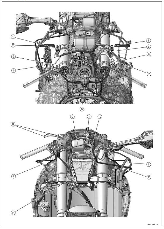
1. Clutch Cable
2. Vacuum Hose (Equipped Models)
3. Left Switch Housing Lead
4. Main Harness
5. Front Brake Hose
6. Throttle Cables
7. Right Switch Housing Lead
8. Bracket (Hold the brake pipes.)
9. Run the meter lead to outside of the meter bracket.
10. Run the vacuum hoses to inside of the meter bracket (equipped models).
11. Clamp (Hold the damper of the front wheel rotation sensor lead.)
KIBS Equipped Models
1. Left Switch Housing Lead
2. Ignition Switch Lead
3. Brake Pipe
4. Alternator Lead
5. Clamp (Hold the brake pipe.)
6. Vacuum Hose (Equipped Models)
7. Fuse Box 1 Lead
8. Run the left switch housing lead and the ignition switch lead to inside of the brake pipe.
9. Front Brake Hose
10. Front Wheel Rotation Sensor Lead
11. Gear Position Switch Lead
12. Fuel Tank Drain Hose
13. Fuel Tank Breather Hose (Other than CAL and SEA-B1 Models)
14. Sidestand Switch Lead
15. Air Cleaner Drain Hose
16. Rear Brake Light Switch Lead
17. Oxygen Sensor Lead
18. Clutch Cable
19. Main Harness
20. Air Bleeder Hose
21. Run the right switch housing lead to inside of the brake pipe.
22. Right Switch Housing Lead
23. Horn Lead
24. Coolant Reserve Tank Overflow Hose
25. Crankshaft Sensor Lead
26. Oil Pressure Switch Lead
KIBS Equipped Models
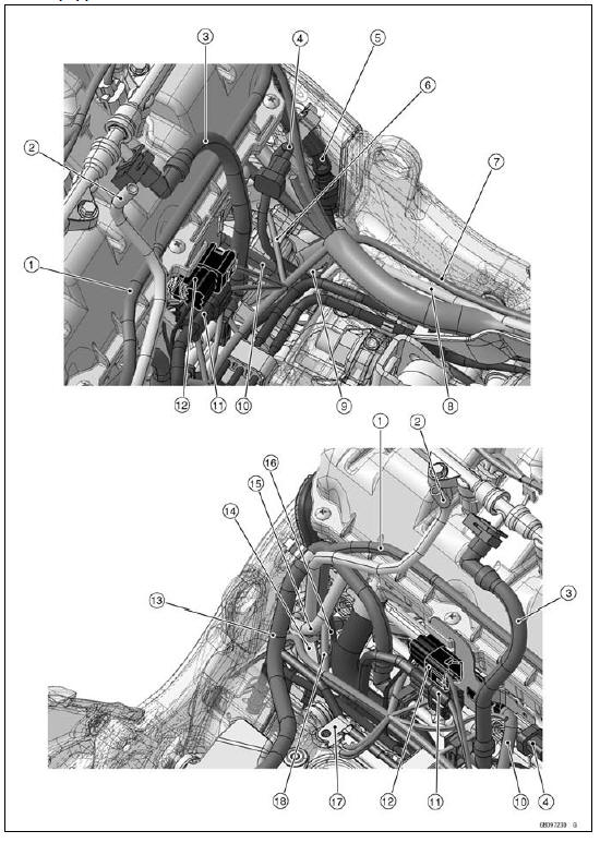
1. Fuel Tank Breather Hose (Other than CAL and SEA-B1 Models)
2. Fuel Tank Drain Hose
3. Secondary Fuel Hose
4. Oxygen Sensor Lead (Equipped Models)
5. Brake Pipe (to Front Master Cylinder)
6. Fuel Injector Lead #4
7. Battery Negative Cable
8. Starter Motor Cable
9. Run the crankshaft sensor lead, the oxygen sensor lead (equipped models), the battery negative cable and the starter motor cable in front of the brake pipe (to front master cylinder).
10. Crankshaft Sensor Lead
11. Gear Position Sensor Lead Connector
12. Engine Sub Harness Connector
13. Primary Fuel Hose
14. KIBS Hydraulic Unit Bracket
15. Run the fuel tank breather hose (Other than CAL and SEA-B1 Models), the fuel tank drain hose and the air cleaner drain hose to left side of the fuel injector lead #1, and run them between the brake pipe (to front caliper) and the KIBS hydraulic unit bracket.
16. Brake Pipe (to Front Caliper)
17. Clamp
18. Fuel Injector Lead #1
KIBS Equipped Models
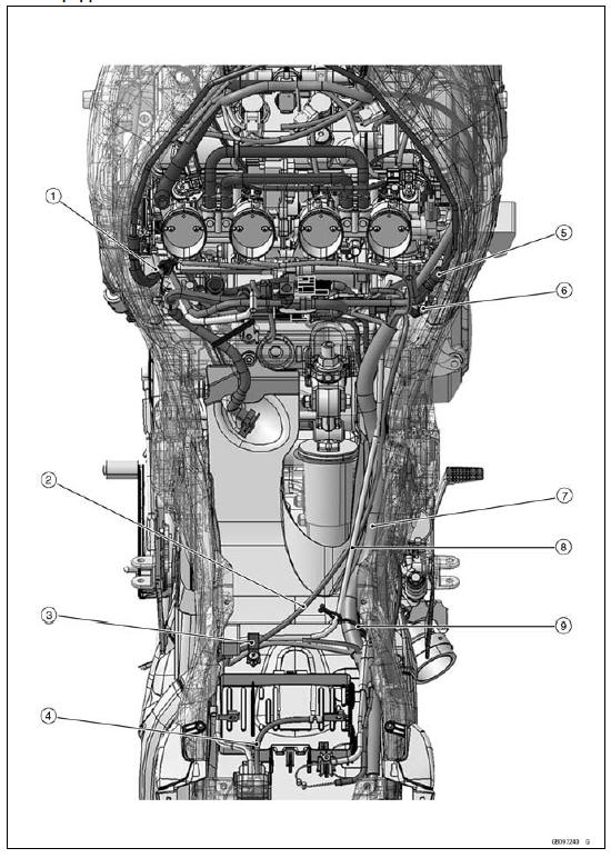
1. Hold the brake hose with the bracket.
2. Battery Negative Cable
3. Clamp (Hold the battery negative cable, the starter motor cable and the turn signal relay lead.)
4. Battery Positive Cable
5. Brake Pipe
6. Clamp (Hold the brake hose. Turn the opening portion upward.)
7. Main Harness
8. Starter Motor Cable
9. Clamp (Hold the main harness and the starter motor cable.)
KIBS Equipped Models
1. White Mark
2. Blue Mark
3. About 64.9°
4. KIBS Hydraulic Unit
5. Clamps (Hold the brake pipe and hose.)
6. Grommet
7. Band
8. Viewed from A
9. Main Harness
10. Brake Pipes
11. About 9.7°
12. Clamp (Hold the front brake hose.)
13. About 16.3°
14. Headlight Mounting Bolt
15. Clamp (Hold the damper of the front wheel rotation sensor lead.)
16. Clamp (Hold the front brake hose and the front wheel rotation sensor lead at the white painted position of the lead. Run the lead in front of the hose.)
17. Clamp (Hold only the front brake hose.)
18. Front Wheel Rotation Sensor
19. Viewed from B
KIBS Equipped Models
1. Green Mark
2. Pink Mark
3. About 51.3°
4. About 25.7°
5. About 0  5 mm (0
 0.2 in.)
6. Clamp (Hold the rear brake hose and the rear wheel rotation sensor lead at the white painted position of the lead. Run the lead to outside of the hose.)
7. Clamp (Hold the rear wheel rotation sensor lead.)
8. Clamp (Hold the rear brake hose and the rear wheel rotation sensor lead at the white painted position of the lead. Run the lead above the hose.)
9. Clamp (Hold the damper of the rear brake hose.)
10. About 88.2°
11. KIBS Hydraulic Unit
12. Rear Wheel Rotation Sensor
13. Run the rear wheel rotation sensor lead to outside of the mud guard.
14. Run the rear brake hose to inside of the mud guard.
15. Clamp (Hold the exhaust butterfly valve cable and the rear wheel rotation sensor lead at the white painted position of the lead. Run the lead in back of the cable.)
16. Run the rear brake hose to inside of the exhaust butterfly valve cables.
17. About 53.8°
18. Run the exhaust butterfly valve cables backside of the stopper.
 ZX1000JC /KC
Models
ZX1000JC /KC
Models CAL and SEA-B1 Models
Mode-switching
Depress the S-KTRC button on the left handlebar switch
to change the mode. The mode can be changed only when
the throttle grip is closed completely.
The S-KTRC OFF can be selected only when the motorcycle
is at a stop. Changing to mode 1 from S-KTRC OFF
is possible while riding.
NOTE
...
Piston Ring End Gap Inspection
Place the piston ring [A] inside the cylinder (upper
crankcase), using the piston to locate the ring squarely
in place. Set it close to the bottom of the cylinder, where
cylinder wear is low.
Measure the gap [B] between the ends of the ring with a
thickness gauge.
Piston Ring End Gap ...
Brake Disc Warp Inspection
Raise the wheel off the ground with the jack.
Special Tools - Jack: 57001-1238
Jack Attachment: 57001-1608
For front disc inspection, turn the handlebar fully to one
side.
Set up a dial gauge against the disc [A] as shown in
the figure and measure disc runout, while turning [B] the
...