
1. This valve seat cutter is developed to grind the valve for repair. Therefore the cutter must not be used for other purposes than seat repair.
2. Do not drop or shock the valve seat cutter, or the diamond particles may fall off.
3. Do not fail to apply engine oil to the valve seat cutter before grinding the seat surface. Also wash off ground particles sticking to the cutter with washing oil.
NOTE
Do not use a wire brush to remove the metal particles from the cutter. It will take off the diamond particles.
4. Setting the valve seat cutter holder in position, operate the cutter in one hand. Do not apply too much force to the diamond portion.
NOTE
Prior to grinding, apply engine oil to the cutter and during the operation, wash off any ground particles sticking to the cutter with washing oil
5. After use, wash it with washing oil and apply thin layer of engine oil before storing.
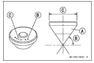
Marks Stamped on the Cutter
The marks stamped on the back of the cutter [A] represent the following.
60° ........................... Cutter angle [B]
37.5  .......................
Outer diameter of cutter [C]
 Valve Seat Repair
 Operating Procedures
Premuffler Chamber Installation
Replace the premuffler chamber gasket [A] with a new
one.
Install the premuffler chamber gasket to the premuffler
chamber [B] until it is bottomed so that the chamfer side
faces exhaust pipe [C].
Install the exhaust pipe clamp [D] as shown in the figure.
Insert the projection [E] into ...
Rear Wheel Rotation Sensor Wiring Inspection (Service Code b 45)
Disconnect the rear wheel rotation sensor lead connector
[A] (see Rear Wheel Rotation Sensor Removal in the
Brakes chapter).
Disconnect the KIBS hydraulic unit lead connector (see
KIBS Hydraulic Unit Removal in the Brakes chapter).
Check the wiring continuity of the G lead and R ...
Service Code Erasing
When repair has been done, warning indicator light (LED) and warning symbol
go off and service
code are not displayed.
But the service codes stored in memory of the ECU are not erased to preserve
the problem history.
In this model, the problem history can not be erased. However, the memorie ...