
NOTE
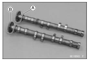
The exhaust camshaft has a 1001 EX mark [A] and the intake camshaft has a 3154 IN mark [B]. Be careful not to mix up these shafts.
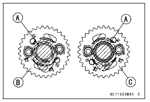
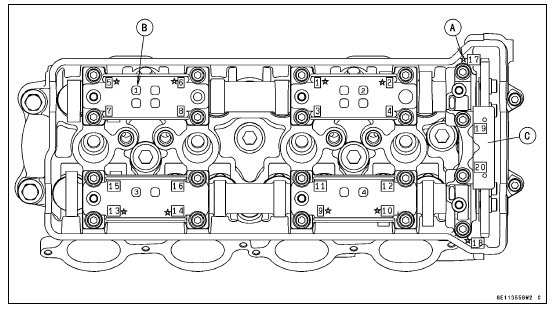
#4 Cam Positions [A] Intake Camshaft Sprocket [B] Exhaust Camshaft Sprocket [C]
The intake camshaft sprocket and exhaust camshaft sprocket are identical
Torque - Camshaft Sprocket Bolts: 15 N·m (1.5 kgf·m, 11 ft·lb)
If a new camshaft is to be used, apply a thin coat of molybdenum disulfide grease to the cam surfaces.
NOTICE
The crankshaft may be turned while the camshafts are removed. Always pull the chain taut while turning the crankshaft. This avoids kinking the chain on the lower (crankshaft) sprocket. A kinked chain could damage both the chain and the sprocket.
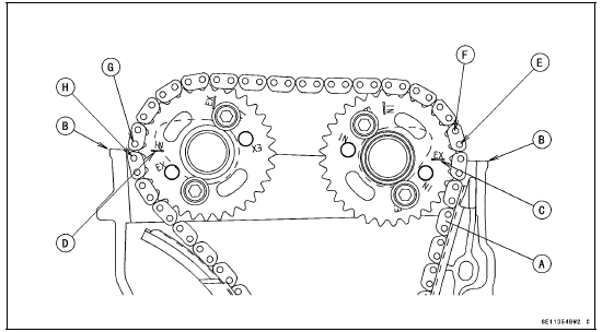
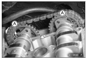
The timing marks must be aligned with the cylinder head upper surface [B].
EX Mark [C] IN Mark [D] #1 Pin [E] #2 Pin [F] #28 Pin [G] #29 Pin [H]
[B] and upper camshaft chain guide [C].
Torque - Camshaft Cap Bolts (1 ∼ 18): 12 N·m (1.2 kgf·m, 106 in·lb) Upper Camshaft Chain Guide Bolts (19, 20): 12 N·m (1.2 kgf·m, 106 in·lb)
 Camshaft Removal
 Camshaft, Camshaft Cap Wear Inspection
Torque Limiter Removal
Remove:
Starter Motor (see Starter Motor Removal in the Electrical
System chapter)
Throttle Body Assy Holder [A]
Breather Hose [B]
Roll up the heat insulation rubber plate [C].
Remove:
Torque Limiter Cover Bolts [A]
Torque Limiter Cover [B]
Remove:
Torque Limit ...
Tire Repair
Currently two types of repair for tubeless tires have come
into wide use. One type is called a temporary (external) repair
which can be carried out without removing the tire from
the rim, and the other type is called permanent (internal)
repair which requires tire removal. It is generally unders ...
Inquiries to Rider
DFI Diagnosis Flow Chart
Each rider reacts to problems in different ways, so it is important to
confirm what kind of symptoms
the rider has encountered.
Try to find out exactly what problem occurred under exactly what
conditions by asking the rider;
knowing this information may h ...