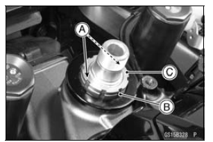


Special Tool - Steering Stem Nut Wrench: 57001-1100
If the steering is too tight, loosen the steering stem nut [B] a fraction of a turn.
If the steering is too loose, tighten the steering stem nut a fraction of a turn.

NOTE
Turn the steering stem nut 1/8 turn at time maximum.

NOTE
Tighten the stem head nut first, then the upper front fork clamp bolts.
Torque - Steering Stem Head Nut: 78 N·m (8.0 kgf·m, 58 ft·lb) Front Fork Clamp Bolts (Upper): 20 N·m (2.0 kgf·m, 15 ft·lb)
| WARNING If the handlebar does not turn to the steering stop it may cause an accident resulting in injury or death. Be sure the cables, harnesses and hoses are routed properly and do not interfere with handlebar movement (see Cable, Wire, and Hose Routing section in the Appendix chapter). |
If the steering is still too tight or too loose, repeat the adjustment.
 Steering Play Inspection
 Steering Stem Bearing Lubrication
Cable Removal
Remove:
Air Cleaner Housing (see Air Cleaner Housing Removal
in the Fuel System (DFI) chapter)
Right Lower Fairing (see Lower Fairing Removal in the
Frame chapter)
Loosen the nuts [A], and slide the lower end of the clutch
cable to give the cable plenty of play.
Screw in the ...
Wear Inspection
Remove the left front footpeg bracket
bolts.
A. Front Footpeg Bracket
B. Bolts
Remove the bolts and chain cover.
A. Bolts
B. Chain Cover
Stretch the chain taut either by using
the chain adjusters, or by hanging a
10 kg (22 lb) weight on the chain.
Measure the lengt ...
Valve Seat Inspection
Remove the valve (see Valve Removal).
Check the valve seating surface [A] between the valve [B]
and valve seat [C].
Measure the outside diameter [D] of the seating pattern
on the valve seat.
If the outside diameter is too large or too small, repair the
seat (see Valve Seat Repair).
Val ...