
1) Overview
This model has an Electronic Steering Damper (ESD) [A]. Unlike conventional manual adjustment method of Kawasaki, damping characteristics are adjusted by the electronic control unit.
2) Purpose
Designed to offer increased stability at high speed without interfering with light and nimble steering at low speed.
3) Advantages
Damping characteristics are properly adjusted by the electronic control unit based on primarily vehicle speed, and additionally acceleration/deceleration.
During public road riding, lighter damping characteristics are selected to preserve the natural nimble handling of this model.
During circuit riding, stiffer damping settings are chosen to enhance stability for better cornering.
Like the public road riding settings, ESD provides the rider with moderate feedback while maintaining natural handling feel. (moderate and natural work fine here) Electronic control is based on speed and acceleration, so at high speeds stability is enhanced.
4) Difference
Change the steering damper damping adjustment method from manual (ZX1000JC/KC) to automatic (Stepper Motor).
Previous Models ( ZX1000JC/KC)
New Models (ZX1000JD/KD)
5) Related Parts
Meter [A] Electronic Steering Damper (ESD) [B]
ESD ECU [A]
FI ECU [B]
Rear Wheel Rotation Sensor [A]
6) Meter
Added an indicator “ESD” warning symbol [A] in the instruments.
The yellow warning indicator light [B] and ESD warning symbol go on whenever there is a malfunction in the ESD system.
At this time, the ESD system maintains the last damping force setting.
7) Error Display
Only Meter Diagnosis
When both “ESD” warning symbol [A] and yellow warning
indicator light [B] go on , the LCD displays service code
[C] by push the upper button [D] at odometer indication
(see Self-Diagnosis Procedures in the Self-Diagnosis System
chapter). 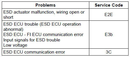
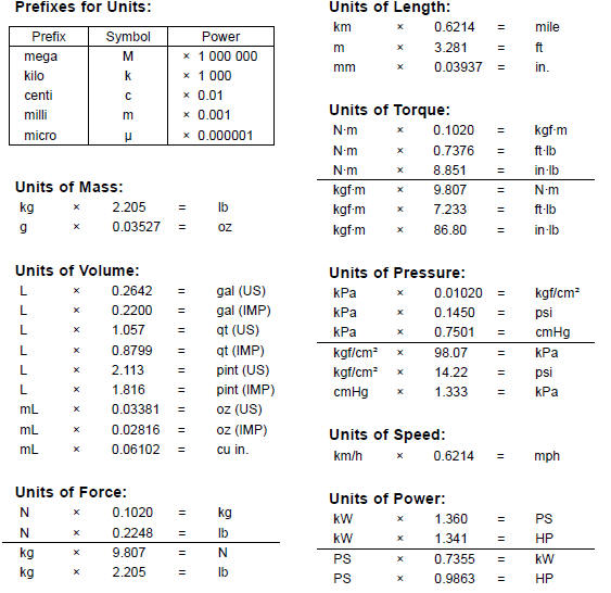
Unit Conversion Table
 Related Parts Locations
Front Fork Oil Change
Remove the front fork (see Front Fork Removal (Each
Fork Leg)).
Turn the spring preload adjuster fully counterclockwise for
removing the piston rod assy easily.
Hold the inner tube lower end in a vise.
Using the wrench [A], unscrew the top plug [B] out of the
outer tube.
Special Too ...
DFI System Troubleshooting Guide
NOTE
This is not an exhaustive list, giving every possible cause for each
problem listed. It is meant
simply as a rough guide to assist the troubleshooting for some of the more
common difficulties in
DFI system.
The ECU may be involved in the DFI electrical and ignition system
tro ...
Axle Inspection
Remove the front and rear axles (see Front/Rear Wheel
Removal).
Visually inspect the front and rear axle for damages.
If the axle is damaged or bent, replace it.
Place the axle in V blocks that are 100 mm (3.94 in.) [A]
apart, and set a dial gauge [B] on the axle at a point
halfway ...
