
Depress the S-KTRC button on the left handlebar switch to change the mode. The mode can be changed only when the throttle grip is closed completely.
The S-KTRC OFF can be selected only when the motorcycle is at a stop. Changing to mode 1 from S-KTRC OFF is possible while riding.
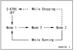
NOTE
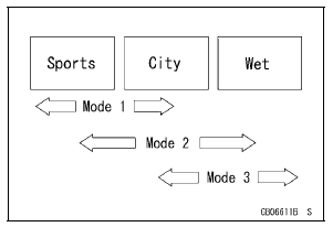
Mode 1: S-KTRC least restrictive among the three modes.
This makes lengthy drifts and wheelies possible when exiting tight corners.
Mode 2: There is more S-KTRC interaction compared to mode 1. This makes slight drifts possible when exiting tight corners.
Mode 3: S-KTRC intervenes to prevent the rear wheel from spinning whenever possible.
 System Components
 Technical Information-Power Mode
Storage of Removed Parts
After all the parts including subassembly parts have been
cleaned, store the parts in a clean area. Put a clean cloth
or plastic sheet over the parts to protect from any foreign
materials that may collect before re-assembly.
Inspection
Reuse of worn or damaged parts may lead to serious acci ...
Air Suction Valve Installation
Install the air suction valve so that opening [A] of the reed
faces downward.
Apply a non-permanent locking agent to the threads of
the air suction valve cover bolts [A], and tighten them.
Torque - Air Suction Valve Cover Bolts: 9.8 N·m (1.0 kgf·m,
87 in·lb)
...
Water Pump Inspection
Remove the left lower fairing (see Lower Fairing Removal
in the Frame chapter).
Check the drainage outlet passage [A] at the bottom of
the water pump body for coolant leaks.
If the mechanical seal is damaged, the coolant leaks
through the seal and drains through the passage. Replace
th ...