
The rider can choose from three engine power modes to suit their preferences and road conditions.
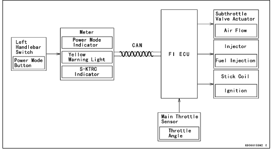
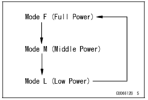
The FI ECU controls the engine power by adjusting fuel injection, air intake, and ignition timing. It enables three-mode selection: Full Power (Mode F), Middle Power (Mode M), and Low Power (Mode L).
In addition, combining each mode with each S-KTRC setting allows the rider to have more choices to be able to interact with various conditions.
Power Mode Operation
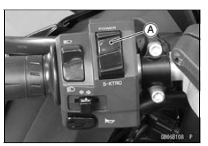
To change the mode, close the throttle grip completely,
and depress the power mode button [A] (0.3
 0.4 sec.).
Power Mode Positions
NOTE
The power mode setting is maintained when the ignition switch is turned OFF, or when the battery is disconnected.
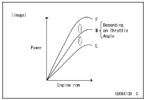
Mode F: The highest engine power output is achieved. The rider can use the full power of the engine.
Mode M: The throttle response is less sharp compared to mode F. Depending on the throttle application, full power can be accessed temporarily.
Mode L: About 60% of the highest engine power output is achieved. The throttle response is mildest among the three modes.
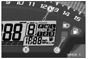
The current mode selection is displayed on the power mode indicator [A] in the multifunction meter.
If a failure occurs with a FI related components such as a subthrottle or main throttle sensor, the warning indicator light (red LED) and FI warning symbol will go ON, and/or the S-KTRC indicator [B] and warning indicator light (yellow LED) [C] blink. The current mode cannot be changed at this time.
 Mode-switching
Seat Cover Installation
Installation is the reverse of removal. Note the following.
When installing the pad [A], install it along the corner [B]
as shown in the figure.
When installing the pad [C], align the ends [D], along the
corner [E], and wrap [F] the upper edge of the seat cover.
Install the damper [A] ...
Cylinder Head Cover Removal
Remove:
Air Suction Valves (see Air Suction Valve Removal)
Throttle Body Assy (see Throttle Body Assy Removal in
the Fuel System (DFI) chapter)
Stick Coils (see Stick Coil Removal in the Electrical System
chapter)
Remove the clamps [A].
Turn up the front side of the heat insulation ...
Subthrottle Valve Actuator Input Voltage Inspection
NOTE
Be sure the battery is fully charged.
Turn the ignition switch to OFF.
Disconnect the subthrottle valve actuator connector and
connect the measuring adapter [A] between these connectors
as shown in the figure.
Main Harness [B]
Subthrottle Valve Actuator [C]
Special Tool ...
