
Screw the needle bearing driver into the driver holder.
Insert the needle bearing driver into the needle bearing and press the needle bearing.
NOTE
For a bearing of inner diameter
 17, select the pressing
side of the needle bearing driver according to its pressing
depth.
Special Tools - Bearing Driver Set: 57001-1129
Needle Bearing Driver,  17/
17/
18: 57001
-1609
NOTE
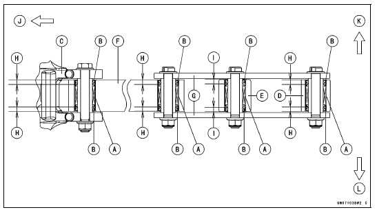
Needle Bearings [A] Oil Seals [B] Frame [C] Rear Shock Absorber [D] Swingarm [E] Tie-rod [F] Rocker Arms [G] 5.5 mm (0.22 in.) [H] 5.9 mm (0.23 in.) [I] Front [J] Right Side [K] Left Side [L]
 Tie-Rod and Rocker Arm Bearing Removal
 Rocker Arm/Tie-Rod Bearing, Sleeve Inspection
Replacement Parts
Replacement parts must be KAWASAKI genuine or
recommended by KAWASAKI. Gaskets, O-rings, oil seals,
grease seals, circlips, cotter pins or self-locking nuts must
be replaced with new ones whenever disassembled.
Assembly Order
In most cases assembly order is the reverse of disassembly,
howe ...
Crankshaft Removal
Split the crankcase (see Crankcase Splitting).
Remove:
Connecting Rod Big End Nuts [A]
Connecting Rod Big End Caps [B]
NOTE
Mark and record the locations of the connecting rods
and their big end caps so that they can be reassembled
in their original positions.
Remove the crank ...
Intake Air Pressure Sensor #2 Installation
NOTE
The intake air pressure sensor #2 is the same part as
the intake air pressure sensor #1.
Installation is basically the reverse of removal.
Position the intake air pressure sensor #2 [A] between the
projections [B] on the rubber damper.
Install the rubber damper [A] on the brac ...