
Special Tools - Bearing Remover Head,
 15 ×
15 ×
 17: 57001
-1267
Bearing Remover Shaft, 13:
13:
57001-1377

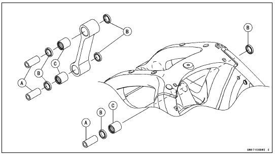
 Rocker Arm Installation
 Tie-Rod and Rocker Arm Bearing Installation
ESD (Electronic Steering Damper) ECU Communication Error (Service Code 3C,
ZX1000JD/KD)
ESD ECU Communication Line Inspection
When the data (for status of ESD system) is not sent from
the ESD ECU to the meter unit and ECU, the service code
3C is displayed.
The data is sent through the CAN communication line.
The service code 3C is detected with the meter unit.
The FI symbol does ...
Rear Shock Absorber Installation
Replace the rear shock absorber nuts and tie-rod nuts
with new ones.
Tighten:
Torque - Rear Shock Absorber Nuts: 34 N·m (3.5 kgf·m, 25
ft·lb)
Tie-Rod Nuts: 34 N·m (3.5 kgf·m, 25 ft·lb)
When installing the rear shock absorber bracket [A], install
it so that the recess side [B] ...
Passenger’s Seat Installation
Insert the tab on the rear of the passenger’s
seat into the slot in the
frame.
Insert the projections at the front of
the passenger’s seat into the holes
on the frame.
Push down the front part of the passenger’s
seat until the lock clicks.
A. Passenger’s Seat
B. Proj ...