
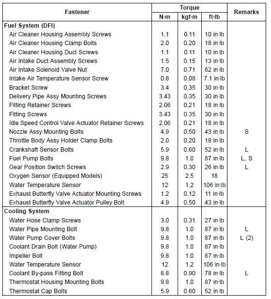
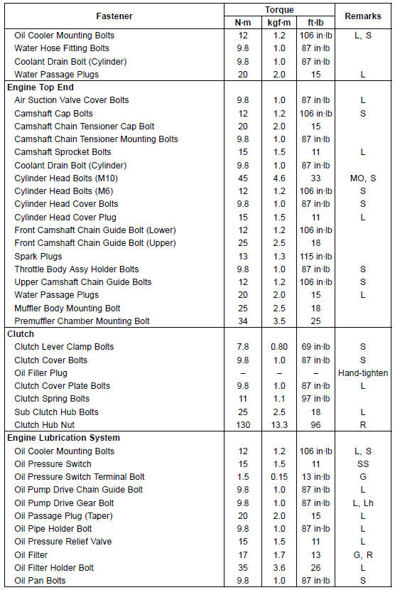
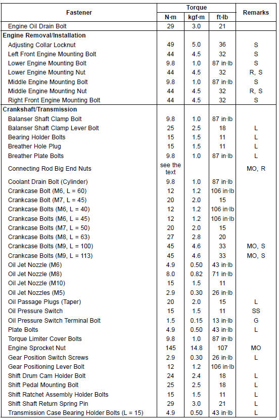
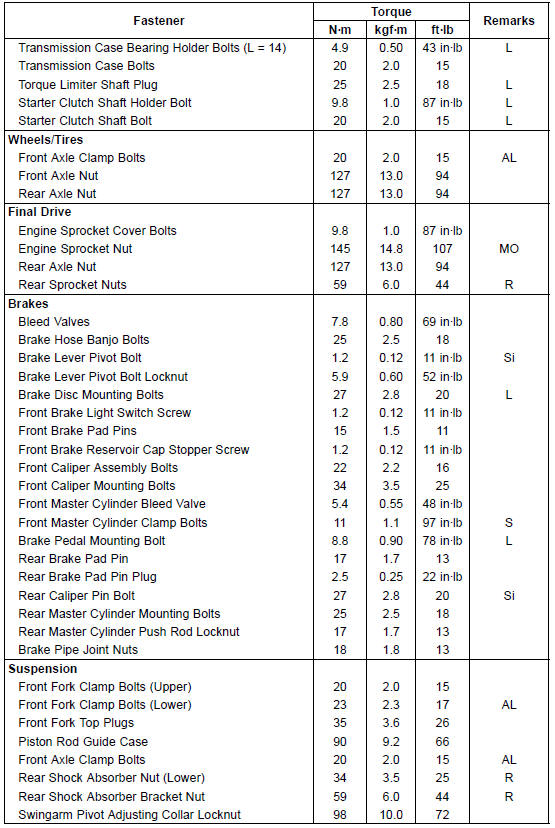
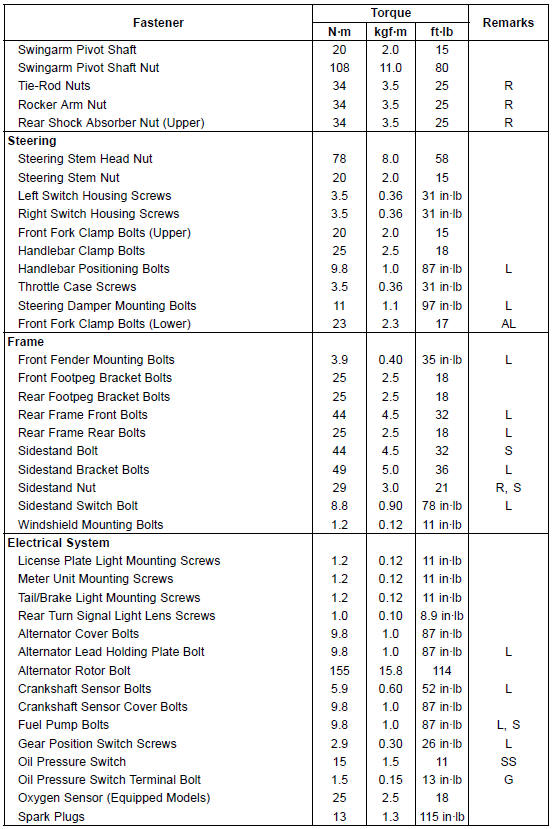
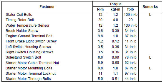
The following tables list the tightening torque for the major fasteners requiring use of a non-permanent locking agent or silicone sealant etc.
Letters used in the “Remarks” column mean: AL: Tighten the two clamp bolts alternately two times to ensure even tightening torque.
G: Apply grease.
L: Apply a non-permanent locking agent.
Lh: Left-hand Threads
MO: Apply molybdenum disulfide oil solution.
(mixture of the engine oil and molybdenum disulfide grease in a weight ratio 10:1)
R: Replacement Parts
S: Follow the specified tightening sequence.
Si: Apply silicone grease (ex. PBC grease).
SS: Apply silicone sealant.
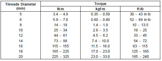
The table below, relating tightening torque to thread diameter, lists the basic torque for the bolts and nuts. Use this table for only the bolts and nuts which do not require a specific torque value. All of the values are for use with dry solvent-cleaned threads.
Basic Torque for General Fasteners
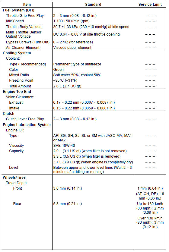
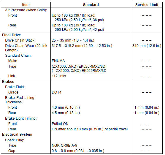
Specifications
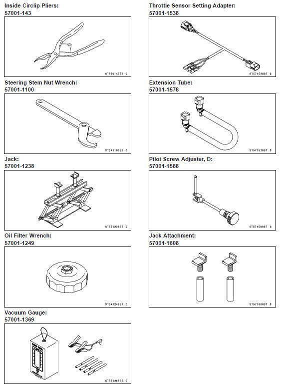
Special Tools
 Periodic Maintenance Chart
Front Master Cylinder Removal
Remove the reservoir mounting bolt and nut [A].
Unscrew the banjo bolt [A] and disconnect the brake hose
from the master cylinder (see Brake Hose and Pipe Replacement
in the Periodic Maintenance chapter).
Unscrew the clamp bolts [B], and take off themaster cylinder
as an assembl ...
Idle Speed Control Valve Actuator Removal
NOTICE
Never drop the idle speed control valve actuator especially
on a hard surface. Such a shock to the actuator
can damage it.
Remove:
Throttle Body Assy (see Throttle Body Assy Removal in
the Fuel System (DFI) chapter)
Idle Speed Control Valve Actuator Retainer Screws [A]
Idle Spe ...
Subthrottle Valve Actuator Resistance Inspection
Turn the ignition switch to OFF.
Disconnect the subthrottle valve actuator connector [A].
Connect a digital meter to the subthrottle valve actuator
connector [A].
Measure the subthrottle valve actuator resistance.
Subthrottle Valve Actuator Resistance
Connections: Y/BK lead [1 ...
