
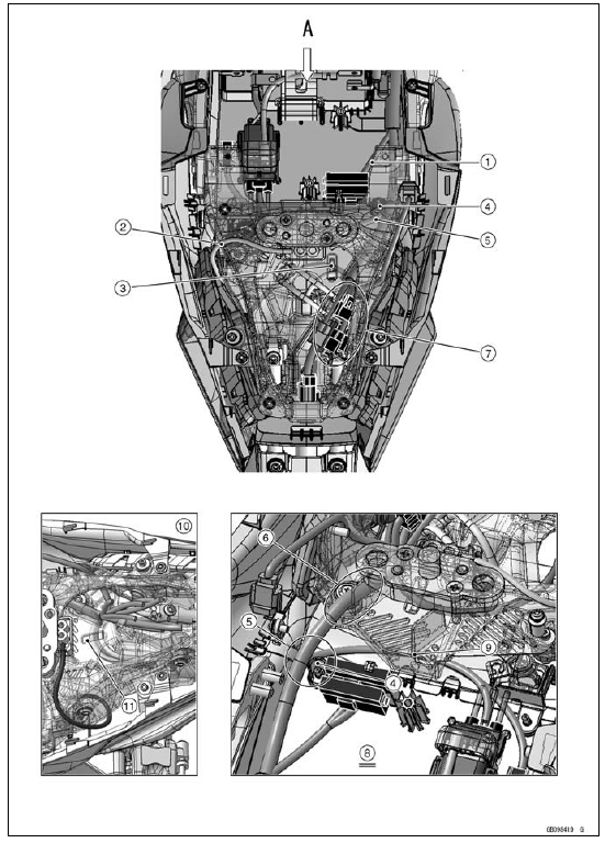
1. Run the fuse box 2 lead in front of the rib for the fuse box 2.
2. Seat Lock Cable
3. Hook the licence plate light lead and the left turn signal light lead on the projection of the tool kit case.
4. Rib for Fuse Box 2
5. Run the starter relay lead in back of the rib for the fuse box 2 and quick rivet. Take care not to stick the quick rivet.
6. Run the main harness between the rib and projection of the tool kit case.
7. Place all connectors into the dust cover.
8. Viewed from A
9. Run the starter relay lead under the tool kit case.
10. US, CA and CAL Models
11. Hook the licence plate light lead, the left and right turn signal light leads on the projection of the tool kit case.
 Cable, Wire, and Hose Routing
 ZX1000JC /KC
Models
ZX1000JC /KC
ModelsSwingarm Removal
Remove:
Rear Wheel (see Rear Wheel Removal in the
Wheels/Tires chapter)
Mud Guard with Rear Brake Hose (see Mud Guard Removal
in the Frame chapter)
Rocker Arm (see Rocker Arm Removal)
Remove:
Brake Hose Clamp Bolt [A]
Unscrew the swingarm pivot shaft nut [A].
Usi ...
Engine No. ZXT00JE003022
1. Heat Insulation Rubber Plate
2. For Air Switching Valve Hoses (Place the air switching valve above the
rubber plate.)
3. For Air Suction Valve Cover
4. For Throttle Body Assy Holder #2 and #3
5. For Throttle Body Assy Holder #1
6. For Water Temperature Sensor
7. Insert the tab into th ...
Brake Disc Installation
Install the brake disc on the wheel so that the marked side
[A] faces out.
Front Brake Discs [B]
Rear Brake Disc [C]
Apply a non-permanent locking agent to the threads of
the brake disc mounting bolts.
Tighten:
Torque - Brake Disc Mounting Bolts: 27 N·m (2.8 kgf·m, 20
...