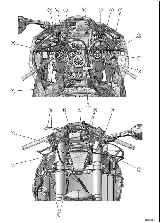


1. Clamp (Hold the regulator/rectifier lead. Run the lead inside of the installation hole.)
2. Clamp (Bend down the clamp, and hold the main harness and the vacuum hose (equipped models).)
3. Clamp (Hold the air intake solenoid valve lead (equipped models).)
4. Run the vacuum hose under the intake solenoid valve lead (equipped models).
5. Clutch Cable
6. Immobilizer Amplifier Lead (Equipped Models)
7. Clamp (Hold the meter unit lead.)
8. Throttle Cables
9. Run the city light lead in front of the meter bracket.
10. Clamp (Bend down the clamp, and hold the main harness and the front wheel rotation sensor lead. Place only the front wheel rotation sensor connector in back of the clamp.)
11. Clamp (Hold the damper of the front wheel rotation sensor lead.)
12. Run the right switch housing lead above the front brake light switch connector.
13. Run the throttle cable (decelerator) to right side of the throttle cable (accelerator). Do not twist the throttle cables.
14. Right Switch Housing Lead
15. Run the meter unit lead to outside of the meter bracket.
16. Run the vacuum hoses to inside of the meter bracket (equipped models).
17. Left Switch Housing Lead

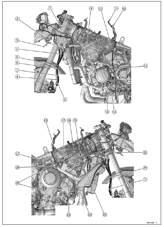
1. Left Switch Housing Lead
2. Run the fuse box 1 lead in front of the fuse box 1.
3. Clamp (Hold the damper of the front wheel rotation sensor lead.)
4. Clamp (Hold the front brake hose and the front wheel rotation sensor lead at the white painted position of the lead. Run the lead in front of the hose.)
5. Clamp (Hold the front brake hose and the front wheel rotation sensor lead. Run the lead in front of the hose.)
6. Clamp (Hold the front brake hose only.)
7. Front Brake Hose
8. Front Wheel Rotation Sensor Lead
9. Alternator Lead
10. Run the gear position switch lead to inside of the heat insulation rubber plate, and run it under the air cleaner hose, and through the space of the part that heat insulation rubber plate matched (US, CA and CAL Models).
11. Fuel Tank Breather Hose (Other than CAL and SEA-B1 Models)
12. Fuel Tank Drain Hose
13. Run the fuel tank drain hose, the fuel tank breather hose (other than CAL and SEA-B1 models) and the air cleaner drain hose to inside of the water hose. Run them to outside of the alternator lead and the sidestand switch lead.
14. Sidestand Switch Lead
15. Air Cleaner Drain Hose
16. Place the heat insulation rubber plate onto the water hose (US, CA and CAL Models).
17. Run the clutch cable along the frame.
18. Run the main harness between the cylinder head and the frame.
19. Run the water hose above the sponge of the heat insulation rubber plate. Take care not to pinch the air bleeding hose to the sponge and the engine (US, CA and CAL Models).
20. Clamp (Hold the horn lead.)
21. Clamp (Hold the front brake hose.)
22. Run the coolant reserve tank overflow hose between the heat insulation plate and the frame, and under the projection of the frame.
23. Run the coolant reserve tank overflow hose into the hole of the heat insulation rubber plate (US, CA and CAL Models).
24. Hook the crankshaft sensor lead to the projection of the crankshaft sensor cover.
25. Hook the oxygen sensor lead (equipped models) to the projections of the clutch cover.
26. Run the crankshaft sensor lead under the water hose, and run it to inside of the clutch cable.
27. When installing the clutch cable, be careful not to put the heat insulation rubber plate between the clutch cable and water hose (US, CA and CAL Models).

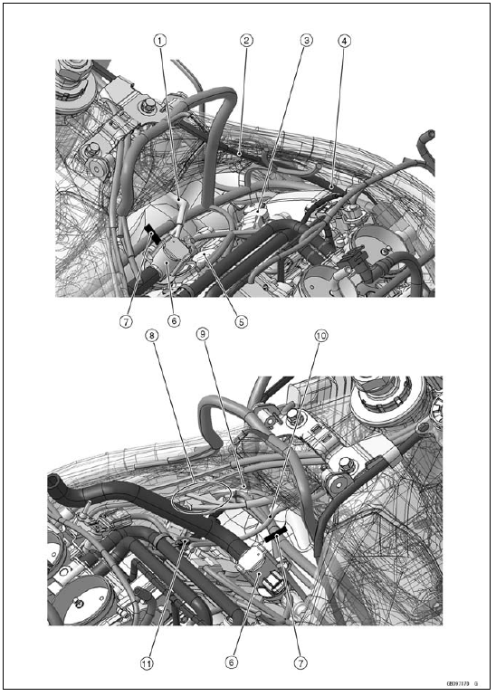
1. Run the right switch housing lead above the main harness.
2. Run the clutch cable along the frame.
3. Stick Coil #4
4. Cross the clutch cable and the main harness near the cylinder head cover, and run the clutch cable between the cylinder head and the frame. Do not run the clutch cable above the cylinder head.)
5. Stick Coil #3
6. Air Switching Valve
7. Clamp (Hold the main harness. Face the opening portion forward. Install it to the heat insulation plate through the heat insulation rubber plate.)
8. Keep the left switch housing lead and the radiator fan lead together as shown in the figure.
9. Run the vacuum hose under the air switching valve hose and the main harness, and run it between the frame and the heat insulation plate (equipped models).
10. Run the ignition switch lead under the air switching valve hose, and run it above the main harness.
11. Clamp (Hold the vacuum hose (equipped models), the ignition switch lead and the immobilizer amplifier lead (equipped models).)

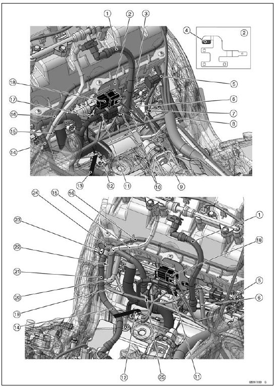
1. Secondary Fuel Hose
2. Connectors Bracket
3. Run the oxygen sensor lead (equipped models) between the connectors bracket and the secondary fuel hose.
4. Stick the pad as shown in the figure.
5. Oxygen Sensor Lead (Equipped Models)
6. Crankshaft Sensor Lead
7. Run the crankshaft sensor lead and the oxygen sensor lead (equipped models) between the fuel injector lead #4 and the secondary fuel hose, and run them in front of the engine sub harness.
8. Clutch Cable
9. Fuel Injector Lead #4
10. Run the gear position switch lead and the engine sub harness in back of the secondary fuel hose.
11. Gear Position Switch Lead Connector
12. Clamp (Hold the rubber band. Face the stopper upward, and install the clamp under the frame ground terminal. Face the frame ground lead to the right side.)
13. Rubber Band
14. Primary Fuel Hose
15. Fuel Tank Drain Hose
16. Fuel Tank Breather Hose (Other than CAL and SEA-B1 Models)
17. Run the engine sub harness in front of the gear position switch lead.
18. Engine Sub Harness Connector
19. Fuel Injector Lead #1
20. Air Cleaner Drain Hose
21. After bring the primary fuel hose forward to prevent pinching, install the fuel tank.
22. Run the fuel tank breather hose (other than CAL and SEA-B1 models), the fuel tank drain hose and the air cleaner drain hose to outside of the fuel injector lead #1.
23. Clamp (Hold the primary fuel hose. Face the opening portion forward.)
24. Run the primary fuel hose in front of the fuel tank breather hose (other than CAL and SEA-B1 models) and the fuel tank drain hose.
25. Run the gear position switch lead and the engine sub harness between the primary fuel hose and the main harness, and run them under the crankcase breather hose.

1. Vacuum Hose (Other than US, CA and CAL Models)
2. Clamp (Hold the white tape position of the main harness.)
3. Clutch Cable
4. Rubber Band
5. Clamp (Hold the rubber band. Face the stopper upward, and install the clamp under the frame ground terminal. Face the frame ground lead to the right side.)
6. Run the battery negative cable and the starter motor cable under the main harness.
7. Run the battery negative cable and the starter motor cable to outside of the main harness.
8. Run the battery negative cable and the starter motor cable above the main harness.
9. Clamp (Hold the main harness, the battery negative cable and the starter cable tightly. Run the main harness to outside of the leads. Cut below the tip of the band 10 mm or less.)
10. Run the main harness to left side of the rib of the rear fender.
11. Clamp (Hold the main harness, the battery negative cable and the starter motor cable.)
12. Clamp (Hold the starter motor cable and the turn signal relay lead. Do not hold the battery negative cable.)
13. Turn Signal Relay
14. Starter Motor Cable
15. Battery Positive Cable
 Appendix
 ZX1000JB/KB Models
Swingarm Installation
Visually inspect the chain guide [A].
Replace the chain guide if it shows any signs of abnormal
wear or damage.
Apply a non-permanent locking agent to the threads of
the chain guide bolt [B].
Apply plenty of grease to the lip of the oil seals [A].
Be sure to install the oil seals ...
Main Throttle Sensor Input Voltage Inspection
NOTE
Be sure the battery is fully charged.
Turn the ignition switch to OFF.
Remove the throttle body assy (see Throttle Body Assy
Removal in the Fuel System (DFI) chapter).
Do not disconnect the connectors of the throttle body
assy.
Disconnect the main throttle sensor connector ...
Coolant Change
WARNINGCoolant can be extremely hot and cause
severe
burns, is toxic and very slippery. Do not remove
the radiator cap or attempt to change the coolant
when the engine is hot; allow it cool completely.
Immediately wipe any spilled coolant from tires,
frame, engine or othe ...