
CAN Communication Line Resistance Inspection
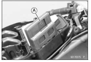
In this model, resistors for CAN communication line are built in the ECU [A] and meter unit.
CAN Communication Line Resistance (at ECU Connector)
Connections: Terminal 27 ←→ Terminal 28
Standard: 123  125 Ω
125 Ω
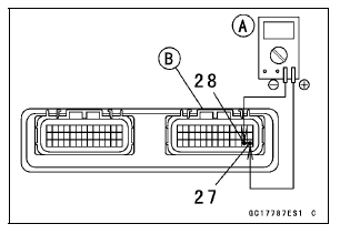
If the reading is out of the range, replace the ECU (see ECU Removal/Installation).
If the reading is within the range, resistor of the ECU for CAN communication line is normal.
Special Tool - Hand Tester: 57001-1394
If the wiring is open, repair or replace the main harness.
CAN Communication Line Circuit
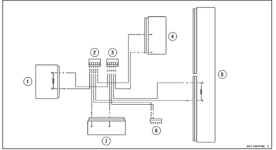
1. Meter Unit
2. Joint Connector C
3. Joint Connector D
4. ESD (Electronic Steering Damper) ECU (ZX1000JD/KD)
5. ECU
6. Immobilizer (Equipped Models)/Kawasaki Diagnostic System Connector
7. KIBS Hydraulic Unit (Equipped Models)
 ECU Power Source Circuit
 DFI Power Source
Swingarm Bearing, Sleeve Inspection
NOTICE
Do not remove the bearings for inspection. Removal
may damage them.
Inspect the needle bearings [A] and ball bearing installed
in the swingarm.
The rollers and ball in a bearing normally wear very little,
and wear is difficult to measure. Instead of measuring,
visually inspec ...
Maintenance and adjustment
The maintenance and adjustments outlined in this chapter must be carried
out in
accordance with the Periodic Maintenance Chart to keep the motorcycle in good
running condition. The initial maintenance is vitally important and must not be
neglected.
With a basic knowledge of mechanics and the ...
Oxygen Sensor Removal (Equipped Models)
Remove:
Fuel Tank (see Fuel Tank Removal in the Fuel System
(DFI) chapter)
Right Lower Fairing (see Lower Fairing Removal in the
Frame chapter)
Disconnect the oxygen sensor lead connector [A].
NOTICE
Do not pull strongly, twist, or bend the oxygen sensor
lead. This may cause the wi ...