
10° [B]
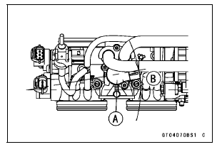
If the idle speed control valve actuator is replaced, be sure to do the following procedures.
Turn the ignition switch to ON.
Turn the ignition switch to OFF, and wait for 2 or 3 seconds.
Inspect the idle speed (see Idle Speed Inspection in the Periodic Maintenance chapter).
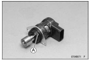
 Idle Speed Control Valve Actuator Removal
 Idle Speed Control Valve Actuator Resistance Inspection
Thermostat Removal
Remove:
Fuel Tank (see Fuel Tank Removal in the Fuel System
(DFI) chapter)
Air Cleaner Housing (see Air Cleaner Housing Removal
in the Fuel System (DFI) chapter)
Throttle Body Assy (see Throttle Body Assy Removal in
the Fuel System (DFI) chapter)
Throttle Body Assy Holder Clamp [A]
...
Rear Wheel Installation
Apply high-temperature grease to the grease seal lips.
Fit the collars on the both sides of the hub.
Left Side Collar [A]
Right Side Collar [B] (with Flange)
Engage the drive chain with the rear sprocket.
Install the caliper bracket [A] onto the stopper [B] of the
swingarm.
...
Tail/Brake Light (LED) Removal/Installation
Remove:
Upper Seat Cover (see Seat Cover Removal in the
Frame chapter)
Disconnect the tail/brake light connector [A].
Remove:
Tail/Brake Light Mounting Screws [A]
Bolts [B] and Brackets [C]
Bolt [D]
Remove the tail/brake light [A].
Bring down the rear fender rea ...