
As the tire tread wears down, the tire becomes more susceptible to puncture and failure. An accepted estimate is that 90% of all tire failures occur during the last 10% of tread life (90% worn). So it is false economy and unsafe to use the tires until they are bald.
If any measurement is less than the service limit, replace the tire (see Tire Removal/Installation in the Wheels/Tires chapter).
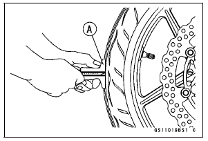
Tread Depth Standard:
Front 3.6 mm (0.14 in.)
Rear 5.3 mm (0.21 in.)
Service Limit:
Front 1 mm (0.04 in.) (AT, CH, DE) 1.6 mm (0.06 in.)
Rear 2 mm (0.08 in.) (Up to 130 km/h (80 mph)) 3 mm (0.12 in.) (Over 130 km/h (80 mph))
| WARNING Some replacement tires may adversely affect handling and cause an accident resulting in serious injury or death. To ensure proper handling and stability, use only the recommended standard tires for replacement, inflated to the standard pressure. |
NOTE
 Wheel/Tire Damage Inspection
 Wheel Bearing Damage Inspection
Cylinder Compression Measurement
NOTE
Use the battery which is fully charged.
Warm up the engine thoroughly.
Stop the engine.
Remove the spark plugs (see Spark Plug Replacement in
the Periodic Maintenance chapter).
Attach the compression gauge [A] and adapter [B] firmly
into the spark plug hole.
Using the startermo ...
Hub Bearing Inspection
Since the hub bearings are made to extremely close tolerances,
the clearance can not normally be measured.
NOTE
Do not remove any bearings for inspection. If any bearings
are removed, they will need to be replaced with
new ones.
Turn each bearing in the hub back and forth [A] while
checki ...
Air Cleaner
A clogged air cleaner restricts the engine’s
air intake, increasing fuel consumption,
reducing engine power, and
causing spark plug fouling.
This motorcycle’s air cleaner element
consists of a wet paper filter, which cannot
be cleaned.
The air cleaner element must be replaced
in acco ...