
NOTE
Be sure the battery is fully charged.
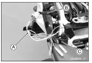
Main Harness [B] Vehicle-down Sensor [C]
Special Tool - Measuring Adapter: 57001-1700
Vehicle-down Sensor Input Voltage Connections to Adapter: Digital Meter (+) → R (sensor BL) lead Digital Meter (–) → BK (sensor BR/BK) lead
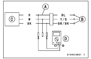
Input Voltage
Standard: DC 4.75  5.25 V
If the reading is within the standard, check the output voltage (see Vehicle-down Sensor Output Voltage Inspection).
If the reading is out of the standard, remove the ECU and check the wiring for continuity between main harness connectors.
Special Tool - Hand Tester: 57001-1394
Disconnect the ECU and sensor connectors.
Wiring Continuity Inspection ECU Connector [A] ←→ Vehicle-down Sensor Connector [B] BL lead (ECU terminal 9) [C] BR/BK lead (ECU terminal 13) [D]
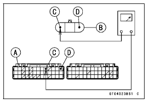
If the wiring is good, check the ECU for its ground and power supply (see ECU Power Supply Inspection in the Fuel System (DFI) chapter).
If the ground and power supply are good, replace the ECU (see ECU Removal/Installation in the Fuel System (DFI) chapter).
 Vehicle-down Sensor Installation
 Vehicle-down Sensor Output Voltage Inspection
Camshaft, Camshaft Cap Wear Inspection
Remove the camshaft caps (see Camshaft Removal).
Cut the strips of plastigage (press gauge) to journal width.
Place a strip on each journal parallel to the camshaft installed
in the correct position.
Tighten the camshaft cap bolts and upper camshaft chain
guide bolts to the specified ...
Premuffler Chamber Installation
Replace the premuffler chamber gasket [A] with a new
one.
Install the premuffler chamber gasket to the premuffler
chamber [B] until it is bottomed so that the chamfer side
faces exhaust pipe [C].
Install the exhaust pipe clamp [D] as shown in the figure.
Insert the projection [E] into ...
Rebound Damping Force Adjustment
To adjust the rebound damping force, turn the rebound
damping adjuster [A].
The standard adjuster setting is the 3 3/4 turns out from
the fully clockwise position.
WARNINGIf both adjusters are not adjusted
equally, handling
may be impaired and a hazardous condition may
res ...