
Apply soap and water solution to the oil level inspection window before installation.
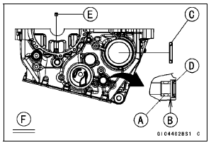
Torque - Oil Passage Plug (Taper): 20 N·m (2.0 kgf·m, 15 ft·lb) Oil Jet Nozzle (M10) [E]: 15 N·m (1.5 kgf·m, 11 ft·lb)
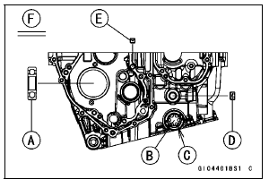
View from Right Side [F]
View from Left Side [F]
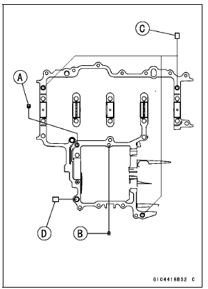
 Upper Crankcase Assembly
 Crankcase Halves Assembly
KIBS Hydraulic Unit Removal
NOTICE
The KIBS hydraulic unit [A] has been adjusted
and set with precision at the factory. Therefore, it
should be handled carefully, never struck sharply,
as with a hammer, or allowed to fall on a hard
surface.
Be careful not to get water or mud on the KIBS hydraulic
unit.
Drain the b ...
Air Cleaner Element Replacement
NOTE
In dusty areas, the element should be replaced more
frequently than the recommended interval.
WARNINGIf dirt or dust is allowed to pass through
into the
throttle body assy, the throttle may become stuck,
possibly causing accident. Replace the air cleaner
element according ...
Parts Location
NOTE
The front and rear wheel rotation sensors and rotors are
standard parts of this motorcycle.
Front Wheel Rotation Sensor [A]
Front Wheel Rotation Sensor Rotor [B]
Rear Wheel Rotation Sensor [C]
Rear Wheel Rotation Sensor Rotor [D]
ABS Indicator Light (LED) [E]
KIBS Indicator Ligh ...