
Air Intake Solenoid Valve Removal/Installation
Air Intake Solenoid Valve Inspection

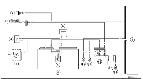
If the air intake solenoid valve [A] is normal, check the wiring for continuity (see Air Intake Solenoid Valve Circuit).
If the wiring is good, check the ECU for its ground and power supply (see ECU Power Supply Inspection in the Fuel System (DFI) chapter).
If the ground and power supply are good, replace the ECU (see ECU Removal/Installation in the Fuel System (DFI) chapter).
Air Intake Solenoid Valve Inspection

1. ECU
2. Air Intake Solenoid Valve
3. Ignition Switch
4. Joint Connector F
5. Joint Connector A
6. Fuse Box 1
7. Ignition Fuse 15 A
8. Relay Box
9. ECU Main Relay
10. Frame Ground 1
11. Frame Ground 3
12. Starter Relay
13. ECU Fuse 15 A
14. Main Fuse 30 A
15. Battery
16. Engine Ground
 Idle Speed Control Valve Actuator Input Voltage Inspection
 ESD (Electronic Steering Damper) ECU Communication Error (Service Code 3C,
ZX1000JD/KD)
ESD (Electronic Steering Damper) ECU Communication Error (Service Code 3C,
ZX1000JD/KD)Exploded View
14. Thermostat
15. Frame No. JKAZXT00JJA003074
or JKAZXCJ1
BA003074
G: Apply grease.
HG: Apply high-temperature grease.
L: Apply a non-permanent locking agent.
R: Replacement Parts
S: Follow the specified tightening sequence.
W: Apply water.
1. US, CA and CAL Models
2. Fra ...
Sidestand Installation
Replace the sidestand nut [A] with a new one.
Apply grease to the sliding areas [B].
Tighten the sidestand bolt [C] first, and then the sidestand
nut.
Torque - Sidestand Bolt: 44 N·m (4.5 kgf·m, 32 ft·lb)
Sidestand Nut: 29 N·m (3.0 kgf·m, 21 ft·lb)
Install the spring [D] as sh ...
Warning/Indicator Lights
: When the
transmission is in
neutral, the neutral indicator light goes
on.
: When the
headlight is on high
beam, the high beam indicator light
goes on.
: When the
turn signal switch is
pushed to the left or right, the turn signal
indicator light blinks. ...