
Mark and record the valve lifter and shim locations so they can be installed in their original positions.
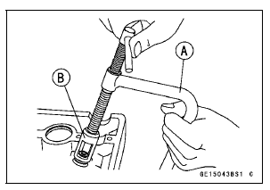
Special Tools - Valve Spring Compressor Assembly [A]: 57001-241
Valve Spring Compressor Adapter, 25 [B]: 57001-1019
Valve Spring Compressor Adapter, 24: 57001-1586
 Valves
 Valve Installation
What is a Limited Warranty?
The most important thing to know about your warranty is that it protects you
from manufacturing defects in material or workmanship during the warranty
period.
You can find the warranty period in the Kawasaki Limited Warranty Certificate
your Kawasaki dealer provided to you at the time of sale ...
US, CA and CAL Models
1. Hold the water hose [A]. Insert the tab into the slot.
2. Hold the water hose [B]. Insert the tab into the slot.
3. Water Hose Fitting on Cylinder Head
4. Heat Insulation Rubber Plate
5. Run the crankshaft sensor lead and the oil pressure switch lead into the
slot, and hook the slot
on ...
Power mode
The Power mode determines the engine
power output characteristics and
has three settings.
The S-KTRC and the Power mode
can be set separately. By combining
each setting, the rider can get various
power feelings to suit riding conditions
or individual preference.
Mode F (Full Power):
The h ...