
If it does, discard it.
| WARNING Unbalanced wheels can create an unsafe riding condition. If the balance weight has any play on the rib of the rim, the blade and/or clip have been stretched. Replace the loose balance weight. Do not reuse used balance weight. |
Balance Weight 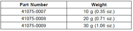
NOTE
An imbalance of less than 10 grams (0.35 oz.) will not usually affect running stability.
Slip the balance weight [A] onto the rib [B] by pushing or lightly hammering [C] the clip [D].
Left Side [E] Right Side [F]
Be sure to install the balance weight.
Check that the blade [A] and clip [B] are fully seated on the rim [C] and that the clip is hooked over the rib [D].
Left Side [E] Right Side [F]
 Balance Weight Removal
 Tires
TiresMaintenance and adjustment
The maintenance and adjustments outlined in this chapter must be carried
out in
accordance with the Periodic Maintenance Chart to keep the motorcycle in good
running condition. The initial maintenance is vitally important and must not be
neglected.
With a basic knowledge of mechanics and the ...
Rear Shock Absorber Inspection
Remove the rear shock absorber (see Rear Shock Absorber
Removal).
Visually inspect the following items.
Smooth Stroke
Oil Leakage
Crack or Dent
If there is any damage to the rear shock absorber, replace
it.
Visually inspect the rubber bushing [A].
If it show any signs o ...
Exploded View
13. Front Wheel Rotation Sensor
B: Apply brake fluid.
L: Apply a non-permanent locking agent.
R: Replacement Parts
S: Follow the specified tightening sequence.
Si: Apply silicone grease (ex. PBC grease).
10. Rear Wheel Rotation Sensor
B: Apply brake fluid.
G: Apply gr ...