
CAN Communication Line Resistance Inspection
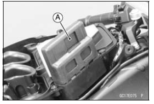
In this model, resistors for CAN communication line are built in the ECU [A] and meter unit.

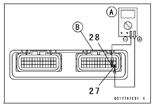
CAN Communication Line Resistance (at ECU Connector)
Connections: Terminal 27 ←→ Terminal 28
Standard: 123  125 Ω
125 Ω

If the reading is out of the range, replace the ECU (see ECU Removal/Installation).
If the reading is within the range, resistor of the ECU for CAN communication line is normal.
Special Tool - Hand Tester: 57001-1394
If the wiring is open, repair or replace the main harness.
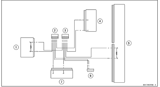
CAN Communication Line Circuit

1. Meter Unit
2. Joint Connector C
3. Joint Connector D
4. ESD (Electronic Steering Damper) ECU (ZX1000JD/KD)
5. ECU
6. Immobilizer (Equipped Models)/Kawasaki Diagnostic System Connector
7. KIBS Hydraulic Unit (Equipped Models)
 ECU Power Source Circuit
 DFI Power Source
Exhaust Butterfly Valve Actuator Inspection
NOTE
Be sure the battery is fully charged
Remove the front seat (see Front Seat Removal in the
Frame chapter).
Turn the ignition switch to ON.
In the left side view of the motorcycle, check to see
the pulley [A] clockwise [B] and counterclockwise [C]
smoothly.
The pulley turns ...
Valve Guide Removal
Remove:
Valve (see Valve Removal)
Oil Seal
Spring Seat
Heat the area around the valve guide to 120
150°C (248
302°F), and hammer lightly on
the valve guide arbor [A]
to remove the guide from the top of the head.
NOTICE
Do not heat the cylinder head with a torch. This ...
Parts Removal/Installation
WARNINGGasoline is extremely flammable and can be
explosive
under certain conditions. Turn the ignition
switch OFF. Do not smoke. Make sure the area is
well-ventilated and free from any source of flame
or sparks; this includes any appliance with a pilot
light.
NOTICE
...