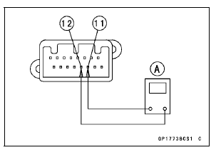

Special Tool - Hand Tester: 57001-1394
CAN Communication Line Resistance (at Meter Unit)
Standard: 122  126 Ω
126 Ω
If the tester reading is not specified, replace the meter unit.

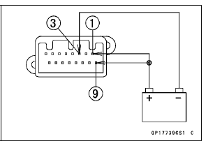
Check 3-2: Meter Unit Power Supply Check
Connect the battery positive (+) terminal to the terminal [1] [9].
Connect the battery negative (–) terminal to the terminal [3].

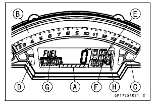
The all LCD segments [A] appear for 3 seconds.
The tachometer (LED) [B] blinks 3 times.
For ZX1000J model, the fuel level warning indicator light (LED) [C] and warning indicator light (Red LED) [D] go on.
For ZX1000K model, the ABS indicator light (LED) [C] and warning indicator light (Red LED) [D] go on.
The following items blinks.
Power Mode Indicator [E] S-KTRC Mode indicator [F] “FUEL” Segment [G] Fuel Level Warning Symbol [H] (ZX1000K model)

 Meter Unit Inspection
 Check 3-3: High Beam Indicator Light (LED) Inspection
Fuel Tank Cap
To open the fuel tank cap, pull up the
key hole cover. Insert the ignition key
into the fuel tank cap and turn the key
to the right.
To close the cap, push it down into
place with the key inserted. The key
can be removed by turning it to the left
to the original position. Close the key
hol ...
Battery Maintenance
It is the owner’s responsibility to keep
the battery fully charged. Failure to do
so can lead to battery failure and leave
you stranded.
If you are riding your vehicle infrequently,
inspect the battery voltage
weekly using a voltmeter. If it drops
below 12.8 volts, the battery should be
...
CAN Communication (Transmission)/CAN Bus OFF Monitor Inspection (Service Code
b 57) CAN Communication (Reception) Monitor Inspection (Service Code b 58)
Remove:
Seat (see Seat Removal in the Frame chapter)
Immobilizer (Equipped Models)/Kawasaki Diagnostic
System Connector Cap [A]
Measure the CAN communication line resistance.
Immobilizer (Equipped Models)/Kawasaki Diagnostic
System Connector [A]
GY/BL Terminal [B]
LB Ter ...