
The standard adjuster setting is the 4 1/2 turns out from the fully clockwise position.
| WARNING If both adjusters are not adjusted equally, handling may be impaired and a hazardous condition may result. Be sure the adjusters are set equally. |
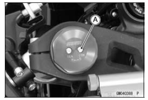
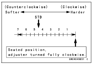
Compression Damping Force Adjustment
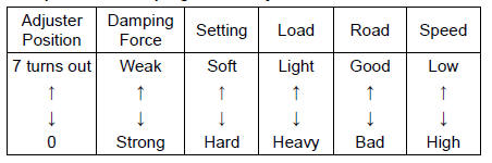
 Rebound Damping Force Adjustment
 Spring Preload Adjustment
Ignition Switch Replacement
Remove:
Air Cleaner Housing (see Air Cleaner Housing Removal
in the Fuel System (DFI) chapter)
Disconnect the lead connectors [A].
Remove:
Steering Stem Head (see Stem, Stem Bearing Removal
in the Steering chapter)
Using a small chisel or punch [A], turn out the Torx bolts.
...
Exhaust Butterfly Valve Actuator Sensor Input Voltage Inspection
NOTE
Be sure the battery is fully charged.
Turn the ignition switch to OFF.
Remove the front seat (see Front Seat Removal in the
Frame chapter).
Remove the screws [A] and the exhaust butterfly valve
actuator temporarily with the cables installed.
Disconnect the exhaust butterf ...
Premuffler Chamber Installation
Replace the premuffler chamber gasket [A] with a new
one.
Install the premuffler chamber gasket to the premuffler
chamber [B] until it is bottomed so that the chamfer side
faces exhaust pipe [C].
Install the exhaust pipe clamp [D] as shown in the figure.
Insert the projection [E] into ...