
NOTE
Do not move the connecting rod and crankshaft during clearance measurement.
Remove the connecting rod big end again, measure each clearance between the bearing insert and crankpin [A] using plastigage (press gauge) [B].
NOTICE
After measurement, replace the connecting rod bolts and nuts.
Connecting Rod Big End Bearing Insert/Crankpin Clearance
Standard: 0.030  0.060 mm
(0.0012  0.0024 in.)
Service Limit: 0.10 mm (0.0039 in.)
If the clearance is within the standard, no bearing replacement is required.
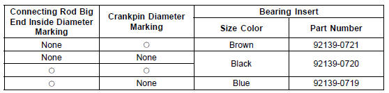
If the clearance is between 0.061 mm (0.0024 in.) and the service limit (0.10 mm, 0.0039 in.), replace the bearing inserts [A] with inserts painted blue [B]. Check insert/ crankpin clearance with the plastigage. The clearance may exceed the standard slightly, but it must not be less than the minimum in order to avoid bearing seizure.
If the clearance exceeds the service limit, measure the diameter of the crankpins.
Crankpin Diameter
Standard: 34.484  34.500 mm
(1.3576  1.3583 in.)
Service Limit: 34.47 mm (1.3571 in.)
Crankpin Diameter Marks
None 34.484  34.492 mm (1.3576
1.3580 in.)
 34.493
 34.500 mm (1.3580
 1.3583 in.)
 : Crankpin Diameter Marks (“” or
No Mark)
NOTE
The mark already on the big end should almost coincide with the measurement.
Connecting Rod Big End Inside Diameter Marks
None 37.500  37.508 mm
(1.4764  1.4767 in.)
 37.509
 37.516 mm (1.4767
 1.4770 in.)
Big End Cap [A] Connecting Rod [B] Weight Mark, Alphabet [C] Diameter Mark [D] (“” or No Mark)
Size Color [B]
 Connecting Rod Big End Side Clearance Inspection
 Crankshaft Side Clearance Inspection
Camshaft Chain Tensioner Removal
NOTICE
This is a non-return type camshaft chain tensioner.
The push rod does not return to its original position
once it moves out to take up camshaft chain slack.
Observe all the rules listed below.
When removing the tensioner, do not take out the
mounting bolts only halfway. Retighteni ...
Lower Crankcase Assembly
Install the ball bearing [A] and the oil level inspection window
[B] until they are bottomed
Apply soap and water solution to the oil level inspection
window before installation.
Install the new circlip [C].
Apply a non-permanent locking agent to the oil passage
plug [D].
Tighten: ...
Piston Ring End Gap Inspection
Place the piston ring [A] inside the cylinder (upper
crankcase), using the piston to locate the ring squarely
in place. Set it close to the bottom of the cylinder, where
cylinder wear is low.
Measure the gap [B] between the ends of the ring with a
thickness gauge.
Piston Ring End Gap ...