
NOTICE
To minimize vibration, the connecting rods should have the same weight mark.
Big End Cap [A] Connecting Rod [B] Weight Mark, Alphabet [C] Diameter Mark [D] (ŌĆ£ŌĆØ or No Mark)
NOTICE
If the connecting rods, big end bearing inserts, or crankshaft are replaced with new ones, select the bearing insert and check clearance with a plastigage (press gauge) before assembling engine to be sure the correct bearing inserts are installed.
NOTICE
Wrong application of oil and grease could cause bearing damage.
When installing the inserts [A], be careful not to damage the insert surface with the edge of the connecting rod [B] or the cap [C]. One way to install inserts is as follows.
Installation [D] to Cap Installation [E] to Connecting Rod Push [F] Spare Dowel Pin [G] Connecting Rod Bolts [H]
The connecting rod big end is bolted using the ŌĆ£plastic region fastening methodŌĆØ.
This method precisely achieves the needed clamping force without exceeding it unnecessarily, allowing the use of thinner, lighter bolts further decreasing connecting rod weight.
There are two types of the plastic region fastening. One is a bolt length measurement method and other is a rotation angle method. Observe one of the following two, but the bolt length measurement method is preferable because this is a more reliable way to tighten the big end nuts.
NOTICE
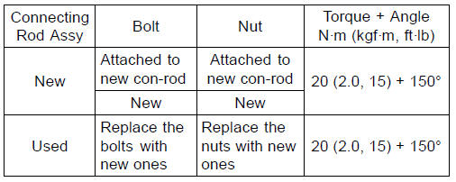
The connecting rod bolts are designed to stretch when tightened. Never reuse the connecting rod bolts. See the table below for correct bolt and nut usage.
NOTICE
Be careful not to overtighten the nuts. The bolts must be positioned on the seating surface correctly to prevent the bolt heads from hitting the crankcase.
(1) Bolt Length Measurement Method
| WARNING Gasoline and low flash-point solvents can be flammable and/or explosive and cause severe burns. Clean the bolts, nuts, and connecting rods in a well-ventilated area, and take care that there are no sparks or flame anywhere near the working area; this includes any appliance with a pilot light. Do not use gasoline or a low flash-point solvent to clean them. |
NOTICE
Immediately dry the bolts and nuts with compressed air after cleaning. Clean and dry the bolts and nuts completely.
If the connecting rod assembly was replaced, use the bolts and nuts attached to the new connecting rod assembly.
Threads [A] of Nuts and Bolts Seating Surfaces [B] of Nuts and Connecting Rods
Connecting Rod [A] Dent here with a punch [B].
Nuts [C] Fit micrometer pins into dents [D].
Bolt Length after tightening ŌĆō Bolt Length before tightening = Bolt Stretch
Connecting Rod Bolt Stretch
Usable Range: 0.24  0.34 mm (0.0094
 0.0134 in.)
If the stretch is more than the usable range, the bolt has stretched too much. An overelongated bolt may break in use.
(2) Rotation Angle Method
If you do not have a point micrometer, you may tighten the nuts using the ŌĆ£Rotation Angle MethodŌĆØ.
| WARNING Gasoline and low flash-point solvents can be flammable and/or explosive and cause severe burns. Clean the bolts, nuts, and connecting rods in a well-ventilated area, and take care that there are no sparks or flame anywhere near the working area; this includes any appliance with a pilot light. Do not use gasoline or a low flash-point solvent to clean them. |
NOTICE
Immediately dry the bolts and nuts with compressed air after cleaning. Clean and dry the bolts and nuts completely.
If the connecting rod assembly was replaced, use the bolts and nuts attached to the new connecting rod assembly.
Threads [A] of Nuts and Bolts Seating Surfaces [B] of Nuts and Connecting Rods
Mark [A] the connecting rod big end caps and nuts so that
nuts can be turned 150┬░ [B] properly.
 Crankshaft Installation
 Crankshaft/Connecting Rod Cleaning
Caliper Installation
Install the caliper and brake hose lower end.
For the front caliper, be sure to install the collars [A].
Replace the washers on each side of hose fitting with new
ones.
Touch the brake hoses [A] to the stopper [B] of the caliper.
Front Calipers [C]
Rear Caliper [D]
Tighten:
To ...
Rear Fender Front Removal
Remove:
Flap and Rear Fender Rear (see Flap and Rear Fender
Rear Removal)
Fuel Tank (see Fuel Tank Removal in the Fuel System
(DFI) chapter)
Battery (see Battery Removal in the Electrical System
chapter)
Exhaust Butterfly Valve Actuator (see Exhaust Butterfly
Valve Actuator Remova ...
Rear Wheel Rotation Sensor Removal
NOTICE
The wheel rotation sensor should be handled carefully,
never struck sharply, as with a hammer, or allowed
to fall on a hard surface since the wheel rotation
sensor is precision made. Be careful not to get
water or mud on the wheel rotation sensor.
Do not try to disassemble or repair t ...