
NOTE
Be sure the battery is fully charged.
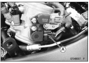
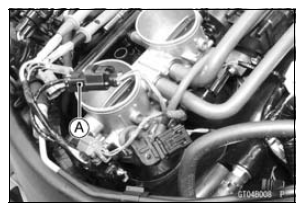
Do not disconnect the connectors of the throttle body assy.
Special Tool - Throttle Sensor Setting Adapter: 57001 -1538
Main Throttle Sensor Input Voltage Connections to Adapter: Digital Meter (+) → W (sensor BL) lead Digital Meter (–) → BK (sensor BR/BK) lead
ECU Intake Air Temperature Sensor
Input Voltage
Standard: DC 4.75  5.25 V
If the reading is within the standard, check the main throttle sensor resistance (see Main Throttle Sensor Resistance Inspection).
If the reading is out of the standard, remove the ECU and check the wiring for continuity between harness connectors.
Special Tool - Hand Tester: 57001-1394
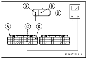
Wiring Continuity Inspection ECU Connector [A] ←→ Main Throttle Sensor Connector [B] BL lead (ECU terminal 9) [C] BR/BK lead (ECU terminal 13) [D]
If the wiring is good, check the ECU for its ground and power supply (see ECU Power Supply Inspection in the Fuel System (DFI) chapter).
If the ground and power supply are good, replace the ECU (see ECU Removal/Installation in the Fuel System (DFI) chapter).
 Main Throttle Sensor Removal/Adjustment
 Main Throttle Sensor Resistance Inspection
Headlight Beam
NOTE
Do not turn the bolts because the reflector
in the headlight comes off.
A. Bolts
The left and right adjusters on the
headlight can move the direction of
the headlight beam to up, down, left
and right by turning each adjuster itself
as the below table.
A. Left Adjuster
...
Lubrication
Lubrication is necessary after riding
through rain or on wet roads, or any
time that the chain appears dry.
Use a lubricant for sealed chains to
prevent deterioration of chain seals. If
the chain is especially dirty, clean it
using a cleaner for sealed chains following
the instructions suppli ...
Exploded View
10. US, CA, CAL and AU Models
11. ZX1000JD/KD
G: Apply grease.
L: Apply a non-permanent locking agent.
R: Replacement Parts
S: Follow the specified tightening sequence.
1. US, CA and CAL Models
2. ZX1000J Model
3. ZX1000K Model
4. AU Model
5. Face the large diameter side re ...