
1. Oil Screen
2. Oil Pump
3. Oil Pressure Relief Valve
4. Oil Filter
5. Oil Pipe
6. Oil Cooler
7. Balancer Oil Passage
8. Main Oil Passage
9. Crankshaft Oil Passage
10. Oil Pressure Switch
11. Camshaft Oil Passages
12. Drive Shaft Oil Passage
13. Output Shaft Oil Passage
14. Starter Clutch Oil Passage
15. Blowby Gas (Crankcase → Air Cleaner Housing)
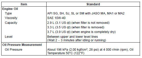
Specifications
 Exploded View
 Special Tools and Sealant
Nozzle Assy Disassembly
Remove the nozzle assy (see Nozzle Assy Removal).
Pull out the secondary fuel injectors [A] from the delivery
pipe assy [B].
NOTE
Do not damage the insertion portions of the injectors
when they are pulled out from the delivery pipe assy.
NOTICE
Never drop the secondary fuel injecto ...
Liquid Gasket, Non-permanent Locking Agent
For applications that require Liquid Gasket or a
Non-permanent Locking Agent, clean the surfaces so
that no oil residue remains before applying liquid gasket or
non-permanent locking agent. Do not apply them excessively.
Excessive application can clog oil passages and
cause serious damage.
...
Storage
Preparation for Storage
Clean the entire vehicle thoroughly
Run the engine for about five minutes to warm the oil, shut it off, and
drain the
engine oil.
WARNINGEngine oil is a toxic substance. Dispose
of used oil properly. Contact
your local authorities for approved disp ...