
NOTE
Be sure the battery is fully charged.
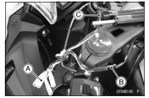
Main Harness [B] ESD Actuator [C]
Special Tool - Peak Voltage Adapter: 57001-1415 Type: KEK-54-9-B
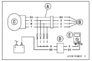
ESD Actuator Input Voltage Connections to Adapter:
(I) Digital Meter (+) → BK (actuator BK) lead Digital Meter (–) → Battery (–) terminal (II) Digital Meter (+) → R (actuator R) lead Digital Meter (–) → Battery (–) terminal (III) Digital Meter (+) → W (actuator O) lead Digital Meter (–) → Battery (–) terminal (IV) Digital Meter (+) → Y (actuator Y) lead Digital Meter (–) → Battery (–) terminal
Input Voltage
Standard: About DC 9  11 V and then
0.1 V or
About DC 9  11 V
11 V
If the reading is out of the specification, remove the ESD ECU and check the wiring for continuity between main harness connector.
Special Tool - Hand Tester: 57001-1394
Disconnect the ESD ECU and actuator connectors.
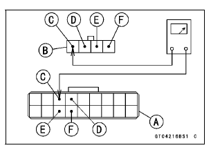
Wiring Continuity Inspection ESD ECU Connector [A] ←→ ESD Actuator Connector [B] BK lead (ESD ECU terminal 3) [C] R lead (ESD ECU terminal 4) [D] O lead (ESD ECU terminal 12) [E] Y lead (ESD ECU terminal 13) [F]
If the wiring is good, check the ESD ECU for its ground and power supply (see ESD ECU Power Supply Inspection).
If the ground and power supply are good, replace the ESD ECU (see ESD (Electronic Steering Damper) ECU Removal/ Installation in the Steering chapter).
ESD Actuator Circuit
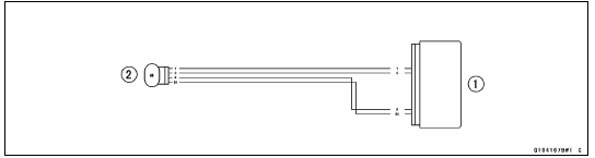
1. ESD ECU
2. ESD Actuator
 ESD Actuator Resistance Inspection
 ESD (Electronic Steering Damper) ECU Error (Service Code E3b, ZX1000JD/KD)
Crankshaft Removal
Split the crankcase (see Crankcase Splitting).
Remove:
Connecting Rod Big End Nuts [A]
Connecting Rod Big End Caps [B]
NOTE
Mark and record the locations of the connecting rods
and their big end caps so that they can be reassembled
in their original positions.
Remove the crank ...
Lighting System
This motorcycle adopt the daylight system and have a
headlight relay in the relay box. The headlight does not
go on when the ignition switch and the engine stop switch
are first turned on. The headlight comes on after the starter
button is released and stays on until the ignition switch is
turn ...
Odometer
The odometer shows the total distance
in kilometers or miles that the vehicle
has run. If the odometer is displayed,
the “ODO” is displayed on the
multifunction display. This meter cannot
be reset.
A. Odometer
B. “ODO”
NOTE
The data are maintained even if the
battery is disco ...