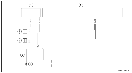

ESD ECU Communication Line Circuit

1. ESD ECU
2. ECU
3. Joint Connector D
4. Joint Connector C
5. Meter Unit
6. Yellow Warning Indicator Light (LED)
 ESD (Electronic Steering Damper) ECU Communication Error (Service Code 3C,
ZX1000JD/KD)
 ESD Actuator Removal
KIBS Warning Indicator Light (For models equipped
with KIBS)
The yellow warning indicator light in
the meter unit functions as the KIBS
warning indicator light. The yellow
warning indicator light and warning
symbol “KIBS” go on if there is a malfunction
in the KIBS system. When the
warning light is on, the KIBS system
stops functioning. However, th ...
Piston Wear Inspection
Measure the outside diameter [A] of each piston 5 mm
(0.20 in.) [B] up from the bottom of the piston at a right
angle to the direction of the piston pin.
If the measurement is under service limit, replace the piston.
Piston Diameter
Standard: 75.959 75.974 mm
(2.9905 2.9911 in.)
...
Troubleshooting Guide
NOTE
Refer to the Fuel System chapter for most
of DFI trouble shooting guide.
This is not an exhaustive list, giving every
possible cause for each problem listed. It
is meant simply as a rough guide to assist
the troubleshooting for some of the more
common difficulties.
Engine Doe ...