Kawasaki Ninja Service Manual: External Shift Mechanism Installation
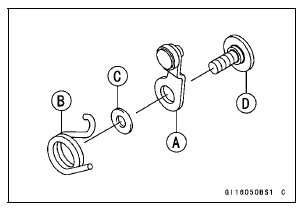
- Install the gear positioning lever [A] as shown in the figure.
- Install:
Spring [B]
Washer [C]
- Tighten:
Torque - Gear Positioning Lever Bolt [D]: 12 N·m (1.2 kgf·m,
106 in·lb)
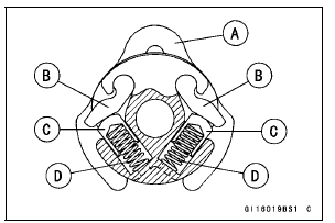
- Assemble:
Ratchet [A]
Pawls [B]
Pins [C]
Springs [D]
- Install the shift ratchet assembly [A] to the holder [B] as
shown in the figure.
- Install the shift ratchet assembly to the shift drum cam [C].
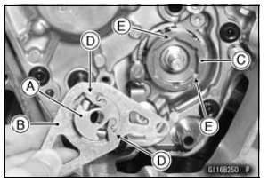
Fit the pawls [D] and the grooves [E].
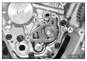
- Set the shift ratchet assembly [A] as shown in the figure.
Turn the shift ratchet assembly while pushing the pawls.
- Apply a non-permanent locking agent to the shift ratchet
assembly holder bolts [B].
- Tighten the shift ratchet assembly holder bolts temporarily.
Tighten the lower bolt first, and then tighten the upper one.
- Tighten:
Torque - Shift Ratchet Assembly Holder Bolts: 15 N·m (1.5
kgf·m, 11 ft·lb)
Tighten the lower bolt first, and then tighten the upper one.
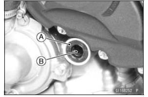
- Replace the oil seal [A] with a new one.
- Apply grease to the lips of the grease seal.
- Apply engine oil to the needle bearing [B].
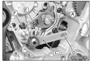
- Install:
Collar [A]
Washer [B]
Shift Shaft Assembly [C]
- Fit the hole [D] and the collar.
- Fit the return spring [E] and the pin [F].
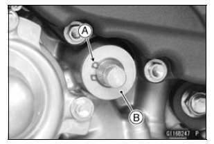
- Replace the circlip [A] with a new one.
- Install:
Washer [B]
Circlip
Special Tool - Outside Circlip Pliers: 57001-144
Fit the circlip into the groove of the shift shaft securely.
Remove:
Shift Lever (see Shift Pedal Removal)
Oil Pump Drive Gear (see Oil Pump Drive Gear Removal/
Installation in the Engine Lubrication System
chapter)
Circlip [A]
Washer [B]
Spec ...
Examine the shift shaft [A] for any damage.
If the shaft is bent, straighten or replace it.
If the serration [B] are damaged, replace the shaft.
If the spring [C] is damaged in any way, replac ...
Other materials:
Exhaust System Identification
Exhaust Pipe Mark Position [A]
Premuffler Chamber Mark Position [A]
Muffler Body Mark Position [A]
Premuffler Chamber [A] with Hole [B] for Oxygen Sensor [C]
Honeycomb Type Catalyst Position [A]
Specifications
...
Tire Repair
Currently two types of repair for tubeless tires have come
into wide use. One type is called a temporary (external) repair
which can be carried out without removing the tire from
the rim, and the other type is called permanent (internal)
repair which requires tire removal. It is generally unders ...
Subthrottle Sensor Output Voltage Inspection
Measure the output voltage at the subthrottle sensor in
the same way as input voltage inspection, note the following.
Disconnect the subthrottle sensor connector and connect
the setting adapter [A] between these connectors.
Special Tool - Throttle Sensor Setting Adapter: 57001
-1538
...


 External Shift Mechanism Removal
 External Shift Mechanism Inspection