
Fuses are arranged in the fuse boxes located under the passenger’s seat and in the left fairing. The main fuse is located under the passenger’s seat.
If a fuse fails during operation, inspect the electrical system to determine the cause, and then replace it with a new fuse of proper amperage.
The main fuse removal should be done by an authorized Kawasaki dealer.
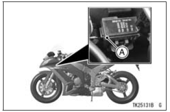
A. Fuse Box
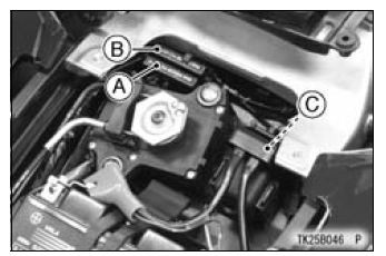
A. Fuse Box
B. Fuse Box (for models equipped with KIBS)
C. Main Fuse
| WARNING Substituting fuses can cause wiring to overheat, catch fire and/or fail. Do not use any substitute for the standard fuse. Replace the blown fuse with a new one of the correct capacity, as specified on the fuse box and main fuse. |
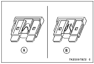
A. Normal
B. Failed
 Headlight Beam
 General Lubrication
Exploded View
5. Other than US, CA, and CAL Models
6. The big diameter side of the dampers faces upward.
G: Apply grease.
L: Apply a non-permanent locking agent.
R: Replacement Parts
S: Follow the specified tightening sequence.
SS: Apply silicone sealant.
11. Immobilizer Ampli ...
Drive Chain Wear Inspection
Remove the chain cover (see Drive Chain Removal/Installation
in the Final Drive chapter).
Rotate the rear wheel to inspect the drive chain for damaged
rollers, and loose pins and links
If there is any irregularity, replace the drive chain.
Lubricate the drive chain if it appears dry.
...
Moving Off
Check that the side stand is up.
Pull in the clutch lever.
Shift into 1st gear.
Open the throttle a little, and start to
let out the clutch lever very slowly.
As the clutch starts to engage, open
the throttle a littlemore, giving the engine
just enough fuel to keep it from
stallin ...