
Case 1: When the ignition key has been lost or additional spare ignition key is required.
Special Tools - Key Registration Unit: 57001-1582 Key Registration Adapter: 57001-1746
Verified
Not Verified
Immobilizer Amplifier Failure
Registered Ignition Key Collation Error
If there are other registered ignition keys, they should all do the procedure above.
The warning indicator light (Red LED) and immobilizer symbol [A] blinks continuously to display that the ECU is in the registration mode for 15 seconds.
NOTE
Insert the ignition key 1 to the ignition switch and turn it to ON.
NOTE
If there is any problem in the registration, the warning indicator light (Red LED) and immobilizer warning symbol [A] blinks to display the collation error.
Immobilizer Amplifier Failure
When Registered Ignition Key is Inserted.
Ignition Key Collation Error

The warning indicator light (Red LED) and immobilizer warning symbol [A] blinks 3 times and stops for 1 second and then repeats this cycle.
The warning indicator light (Red LED) and immobilizer warning symbol [A] blinks to display the registration mode.
NOTE
Insert the ignition key 2 to the ignition switch and turn it to ON.
If there is any problem in the registration, the warning indicator light (Red LED) and immobilizer warning symbol [A] blinks to display the collation error.
Immobilizer Amplifier Failure
When Registered Ignition Key is Inserted.
Ignition Key Collation Error

The warning indicator light (Red LED) and immobilizer warning symbol [A] blinks 4 times and stops for 1 second and then repeats this cycle.
This procedure has registered the registered and 2 ignition keys.
NOTE
The ECU can store up the five key codes.
Ignition Key Indicator Light and Symbol Blinks
NOTE
Spare Ignition Key Registration Flow Chart
Case 2: When the ignition switch is faulty and to be replaced.
These parts are available as a set. Prepare the current registered ignition key [C].
Special Tools - Key Registration Unit: 57001-1582 Key Registration Adapter: 57001-1746
ECU Relay Box Intake Air Temperature Sensor
NOTE
Keep the ignition switches more than 15 cm (5.9 in.).
[C] New Ignition Switch [D] Current Ignition Switch
Verified
The warning indicator light (Red LED) and immobilizer warning symbol [A] blinks to display the ECU is in the registration mode (go to the next step).

Not Verified
Immobilizer Amplifier Failure
Registered Ignition Key Collation Error
NOTE
If there is any problem in the registration, the warning indicator light (Red LED) and immobilizer warning symbol [A] blinks to display the collation error.
Immobilizer Amplifier Failure
When Registered Ignition Key is Inserted.

Ignition Key Collation Error

The warning indicator light (Red LED) and immobilizer warning symbol [A] blinks 2 times and stops for 1 second and then repeats this cycle to indicate successful registering of the ignition key 1.
The warning indicator light (Red LED) and immobilizer warning symbol [A] blinks to display the registration mode.
NOTE
Insert the ignition key 2 to the ignition switch and turn it to ON.
If there is any problem in the registration, the warning indicator light (Red LED) and immobilizer warning symbol [A] blinks to display the collation error.
Immobilizer Amplifier Failure
When Registered Ignition Key is Inserted.
Ignition Key Collation Error
The warning indicator light (Red LED) and immobilizer warning symbol [A] blinks 3 times and stops for 1 second and then repeat this cycle to indicate successful programming of ignition key 2.
NOTE
Install the new ignition switch (see Immobilizer System Parts Replacement).
Case 3: When the ECU is faulty and has to be replaced.
NOTE
Replace the ECU [A] (see ECU Removal/Installation in the Fuel System (DFI) chapter).
If there is any problem in the registration, the warning indicator light (Red LED) and immobilizer warning symbol [A] blinks to display the collation error.
Immobilizer Amplifier Failure
Registered Ignition Key Collation Error

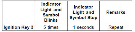
The warning indicator light (Red LED) and immobilizer warning symbol [A] blinks 1 time and stops for 1 second and the repeats this cycle to indicate successful registration of the registered ignition key.
The warning indicator light (Red LED) and immobilizer warning symbol [A] blinks to display the registration mode.
NOTE
Insert the other remaining registered ignition key to the ignition switch and turn it to ON.
NOTE
Keep the other ignition keys away from the immobilizer antenna.
If there is any problem in the registration, the warning indicator light (Red LED) and immobilizer warning symbol [A] blinks to display the collation error.
Immobilizer Amplifier Failure
When Registered Ignition Key is Inserted.
Ignition Key Collation Error
The warning indicator light (Red LED) and immobilizer warning symbol [A] blinks 2 times and stops for 1 second and then repeats this cycle to indicate successful registration of the second ignition key.
NOTE
Case 4: When all registered ignition keys are faulty or lost.
The all registered ignition keys replacement is considered very rare case. However if it is required, the following is necessary.
NOTE
The ECU must be replaced with a new one because the registered ignition key code that is registered in the current ECU can not be rewritten.
NOTE
If there is any problem in the registration, the warning indicator light (Red LED) and immobilizer warning symbol [A] blinks to display the collation error.
Immobilizer Amplifier Failure
Ignition Key Collation Error

The warning indicator light (Red LED) and immobilizer warning symbol [A] blinks 1 time and stops for 1 second and the repeats this cycle to indicate successful registration of the first ignition key.

NOTE
NOTE
Keep the other ignition keys away from the immobilizer antenna.
If there is any problem in the registration, the warning indicator light (Red LED) and immobilizer warning symbol [A] blinks to display the collation error.
Immobilizer Amplifier Failure
When Registered Ignition Key is Inserted
Ignition Key Collation Error
The warning indicator light (Red LED) and immobilizer warning symbol [A] blinks 2 times and stops for 1 second and then repeats this cycle to indicate successful registration of second ignition key.
NOTE
All Keys Initial Registration Flow Chart
 Operational Cautions
KIBS Equipped Models
1. Clutch Cable
2. Vacuum Hose (Equipped Models)
3. Left Switch Housing Lead
4. Main Harness
5. Front Brake Hose
6. Throttle Cables
7. Right Switch Housing Lead
8. Bracket (Hold the brake pipes.)
9. Run the meter lead to outside of the meter bracket.
10. Run the vacuum hoses to inside o ...
Operational Cautions
1. Do not put two keys of any immobilizer system on the same key ring.
2. Do not submerge any key in water.
3. Do not expose any key to excessively high temperature.
4. Do not place any key close to magnet.
5. Do not place a heavy item on any key.
6. Do not grind any key or alter its ...
Turn Signal Switch
When the turn signal switch is
pushed to the left ( ) or right
( ), the corresponding turn signals
blink on and off.
To stop blinking, push the switch in.
Horn Button
When the horn button is pushed, the
horn sounds
LAP/Passing Button
When the LAP/passing button is
pushed, the headlight hi ...
