
NOTICE
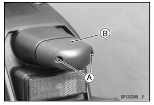
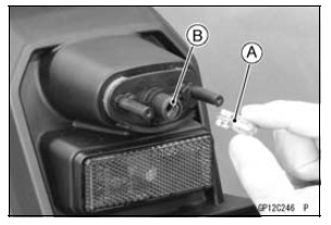
Do not turn the bulb. Pull the bulb out to prevent damage to the bulb. Do not use bulb rated for greater wattage than the specified value.
Headlight/Tail Light Circuit
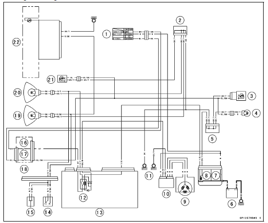
1. Ignition Switch
2. Joint Connector A
3. Tail/Brake Light (LED)
4. License Plate Light 12 V 5 W
5. Joint Connector B
6. Battery
7. Main Fuse 30 A
8. Starter Relay
9. Alternator
10. Regulator/Rectifier
11. Frame Grounds
12. Headlight Circuit Relay
13. Relay Box
14. Dimmer Switch
15. Passing Button
16. Headlight Relay Fuse 15 A
17. Turn Signal Relay Fuse 10 A
18. Fuse Box #1
19. Headlight (HI) 12 V 55 W
20. Headlight (LO) 12 V 55 W
21. City Light (LED)
22. High Beam Indicator Light (LED)
Front Turn Signal Light Removal
Refer to the Upper Fairing Assembly Removal.
Front Turn Signal Light Installation
Refer to the Upper Fairing Assembly Installation.
 Tail/Brake Light (LED) Removal/Installation
 Rear Turn Signal Light Bulb Replacement
Front Fork Disassembly
Remove the front fork (see Front Fork Removal (Each
Fork Leg))
Drain the fork oil (see Front Fork Oil Change).
Take the dust seal [A] off the outer tube.
Remove the retaining ring [B].
Separate the outer tube from the inner tube.
Remove the following parts from the inner tube. ...
Subthrottle Valve Actuator Input Voltage Inspection
NOTE
Be sure the battery is fully charged.
Turn the ignition switch to OFF.
Disconnect the subthrottle valve actuator connector and
connect the measuring adapter [A] between these connectors
as shown in the figure.
Main Harness [B]
Subthrottle Valve Actuator [C]
Special Tool ...
Clutch Plate Warp Inspection
Place each friction plate or steel plate on a surface plate
and measure the gap between the surface plate [A] and
each friction plate or steel plate [B] with a thickness gauge
[C]. The gap is the amount of friction or steel plate warp.
If any plate is warped over the service limit, repla ...