Kawasaki Ninja Service Manual: Rear Turn Signal Light Bulb Replacement
- Remove the upper seat cover (see Seat Cover Removal
in the Frame chapter).
- Disconnect the tail/brake light connector [A].
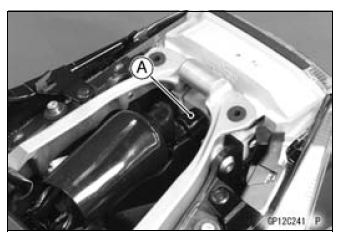
- Turn the socket [A] counterclockwise and remove the
socket together with the bulb.
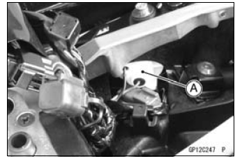
- Push and turn the turn signal light bulb [A] counterclockwise
and remove it.
- Replace the bulb with a new one.
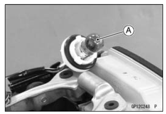
- Insert the new bulb [A] by aligning its pins [B] with the
grooves [C] in the socket, and turn the bulb clockwise
securely.
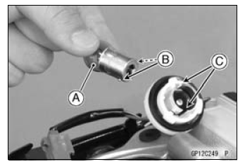
- Fit the tabs [A] of the socket into the grooves [B] of the
turn signal light housing.
- Turn the socket clockwise.
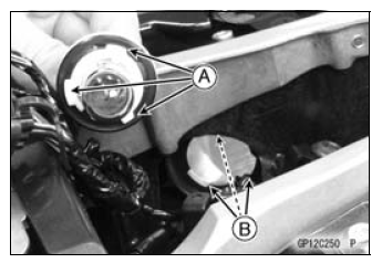
Another Bulb: Repeat the above steps.
US, CA and CAL Models
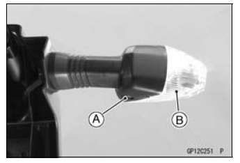
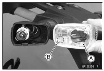
- Remove:
Screw [A]
Rear Turn Signal Light Lens [B]
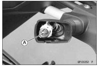
- Push and turn the turn signal light bulb [A] counterclockwise
and remove it.
- Replace the bulb with a new one.
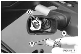
- Insert the new bulb [A] by aligning its pins [B] with the
grooves [C] in the socket, and turn the bulb clockwise
securely.
Check that the “R” (Right) or “L” (Left) mark [B].
- Tighten:
Torque - Rear Turn Signal Light Lens Screws: 1.0 N·m(0.10
kgf·m, 8.9 in·lb)
Another Bulb: Repeat the above steps.
Remove:
Screws [A]
License Plate Light Cover [B]
Pull the bulb [A] out of the socket [B].
NOTICE
Do not turn the bulb. Pull the bulb out to prevent
damage to the bulb. Do not use ...
Remove the battery (see Battery Removal).
Take the turn signal relay [A] off the rear fender.
Disconnect the connector [B].
Connect one 12 V battery and turn signal lights as indicate ...
Other materials:
Battery Ground
Before completing any service on the motorcycle, disconnect
the battery cables from the battery to prevent the engine
from accidentally turning over. Disconnect the ground
cable (–) first and then the positive (+). When completed
with the service, first connect the positive (+) cable to the
p ...
Tire Tread Wear Inspection
As the tire tread wears down, the tire becomes more susceptible
to puncture and failure. An accepted estimate is
that 90% of all tire failures occur during the last 10% of tread
life (90% worn). So it is false economy and unsafe to use
the tires until they are bald.
Measure the tread depth a ...
Chain Slack Adjustment
Remove the cotter pin, and loosen
the axle nut.
Loosen the left and right chain adjuster
locknuts.
A. Axle Nut
B. Cotter Pin
C. Adjuster
D. Locknut
If the chain is too loose, turn out the
left and right chain adjusters evenly.
If the chain is too tight, turn in the left
...


 License Plate Light Bulb Replacement
 Turn Signal Relay Inspection